


F10 Installation Manual
Rev. *60
57 of 71
Configuring the System for Asynchronous Noise
Filter View A shows excessive ‘spiky’ noise, which can also occur from a sweeper. This results in
poor tag detection as the output filter display (Filter View 'D') will bounce as much as ½ a division.
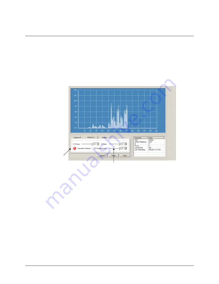
Figure 6.2 shows the Analog View (Filter View A) displaying the noise. This view is directly from
the output of the ADC and is controlled only by the hardware gain (RF gain). Gain for filter views
C and D are also control by the RX gain (software gain). This is important because if the system is
saturated before the signal is processed (before the ADC, but after the hardware receiver), the RF
gain will need to be reduced. For cases when the TX control is disabled (customers using non-
deactivatable tags), the RF gain should be reduced until the Saturation Indicator LED is not lit.
This graph shows the Analog View with a sweeper 8 feet away from the submaster electronics.
Active Saturation
Indication LED
RX Hardware Gain Control
Figure 6.2
Noise on Filter A View RX and RX Hardware Gain @ 31
If the TX Control is enabled, using the Saturation Indicator is not enough – additional RF gain
reduction could be necessary. To reduce the RF gain and attempt to resolve such a condition,
follow the steps below.
1.
Observe the signal level (being shown in Filter View A) for about 15-30 seconds and
make a note of the highest level (peak response) during this period.
2.
Reduce the RF gain until the peak response is only about one division. Below is a picture
after the adjustment.


