background image

–16 –

6.3  Verifying the calibration

When verifying the calibration, make sure to select the same material, calibration 
position and calibration points as used for creating the associated material characteristic. 
Otherwise, the precision of the measurements will not be sufficient.

The tension meter has been calibrated on material 1 according our factory procedure for 
a vertical material path and cannot be deleted or overwritten. The diameter and material 
is given in chapter 2. Calibrations of the tension meter are performed according to the 
factory procedure using weights that correspond to 10%, 50% and 90% of the measuring 
range.

1.  Attach a weight vertically to the material to be measured that corresponds to the  
 

tension to be measured (make sure to select the correct unit). The weight must hang  


freely. (Always use a fresh portion of the material to be measured.)

2.   Insert the material as described in chapter 5.2. 

Do not let the lever snap back as this could affect the calibration  
and damage the instrument.


3.   Before verifying the calibration, move the instrument slowly up and down to    
 

compensate for any mechanical friction losses and thus ensure repeatability of  


the measurements.

4.  The tension value shown on the display should be equal to the mass of the  


suspended weight.

NOTE: 

If the verification of the calibration shows a deviation beyond the allowable 

tolerance so that reliable operation is no longer possible, the instrument needs to be 
re-calibrated or returned to the factory for repair.

Summary of Contents for ETB

Page 1: ...MODEL ETB ETPB TENSION METERS Operating Manual ...

Page 2: ...nu 4 2 Passwor 4 3 Factory reset 5 0 Operating procedure 10 5 1 Zero adjustment of the measurement position 5 2 Inserting and removing material to be measured 5 3 Damping 5 4 Using the alarm function 5 5 Cal Adjustment 6 0 Creating a material characteristic 13 6 1 Setup for calibration 6 2 Calibration procedure 6 3 Verifying the calibration 7 0 Memory functions 17 7 1 Save data 7 2 Displaying the ...

Page 3: ...autions The device must not be operated in potential explosive areas and must not come into contact with aggressive substances Tensions that exceed the tension range of the instrument by more than 100 may cause permanent damage to the measuring spring and must be avoided under any circumstances For cleaning the unit do not use any aggressive solvents such as trichloroethylene or similar chemicals ...

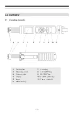
Page 4: ... 3 2 0 OVERVIEW 2 1 Operating elements 1 Guide rollers 2 Measuring rollers 3 Filament guide 4 Display 5 Lever 6 MEMORY key 7 Arrow key 8 SET DAMP key 9 ESC EXIT key 10 POWER ZERO key 11 Power connector ...

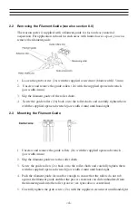
Page 5: ...ully tighten them with the supplied open end wrench jaw width 4 mm until hand tight 2 3 Mounting the Filament Guide 1 Unscrew and remove the guide rollers 2x with the supplied open end wrench jaw width 4 mm 2 Slip the filament guide on to the roller shafts 3 Screw the guide rollers 2x back on to the roller shafts and carefully tighten them with the supplied open end wrench jaw width 4 mm until han...

Page 6: ... 5 2 4 Display elements Numeric Display Display with Bar Graph ...

Page 7: ...rox 1 3 of MAX alarm value and minus approx 1 3 of MIN alarm value if limit values are entered and the damping is not activated With the or button the X axis can be scaled The setting range is 2 to 60 sec The scaling can also be changed during the measurement whereby values already displayed are deleted when the X axis is changed 6 ...

Page 8: ...dapter cable to the USB output The battery can also be charged by connecting the USB cable to a PC The battery level indicator will be shown full when the battery is fully chaarged The charging time is approx 3 hours using the AC adapter NOTE Battery overcharging is not possible 3 2 Switching the tension meter on 1 Press and hold the button for approx 1 sec until the DISPLAY shows the measuring ra...

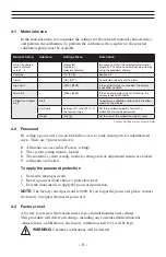
Page 9: ...asured value displayed as graphical trend Alarms ON OFF Activate deactivate the alarm for all calibra tions The alarm of a material characteristic is only ac tive if the Alarm menu item in Material Setup is activated as well Display Settings Backlight ON OFF Switch the display light on or off With the AUTO setting the light switches on and off au tomatically depending on the ambient light Brightne...

Page 10: ... range Set three calibration points for which a calibration should be performed Weight cN g Set the unit of the calibration weights used Factory Settings are illustrated in bold 4 2 Password By setting a password you can block the access to some menu parts for unauthorized users There are 3 protection levels 0 All menus are accessible Factory setting 1 The system setting menu is locked 2 The mater...

Page 11: ...material to be measured must have been inserted yet To carry out zero adjustment 1 Switch on the tension meter 2 Bring the tension meter into the desired measuring position and make sure not to move it 3 Press the button The Display momentarily shows and then switches to The tension meter is now adjusted to its new measuring position and ready to take measurements 5 2 Inserting and removing materi...

Page 12: ... button to increase the damping value or the button to decrease it Changes made to the damping factor using the arrow keys are not saved permanently in the material characteristic If you disable the damping feature or select a different material characteristic the damping factor will be reset to the value originally saved for the material characteristic The factory setting for the damping factor i...

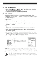
Page 13: ...the Cal Adjustment menu item from the main menu see figure below 2 Insert the material to be measured section 5 2 and push the thumbpiece into the measuring position 3 Press the or key to perform the calibration adjustment until the value on the display corresponds to the weight suspended to the material The adjustment can be performed in 1 steps within the range from 10 to 1 4 Press the button to...

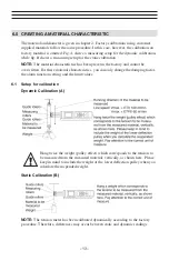
Page 14: ...y and cannot be overwritten For these material characteristics you can only change the damping factor the alarm function setting and the limit values 6 1 Setup for calibration Dynamic Calibration A Static Calibration B NOTE The tension meter has been calibrated dynamically according to the factory procedure Therefore differences may occur between static and dynamic readings Hang twice the weight p...

Page 15: ... calibration must correspond to 10 40 and 70 for the dynamic calibration 20 80 und 140 of the measuring range In this example you need the following weights for the ETX 100 Static calibration in Newton 10 cN 40 cN and 70 cN Static calibration in Gram 10 g 40 g and 70 g Dynamic calibration in Newton 20 cN 80 cN and 140 cN Dynamic calibration in Gram 20 g 80 g and 140 g NOTE The measured values are ...

Page 16: ... repeat the calibration using other calibration points We recommend that you align the middle of the tension range to be measured with the middle calibration point Step 2 Perform a zero adjustment with the tension meter in its measuring position Step 3 Calibrate calibration point 1 Insert material to be measured Step 4 Calibrate calibration point 2 Step 5 Calibrate calibration point 3 NOTE Once yo...

Page 17: ... vertically to the material to be measured that corresponds to the tension to be measured make sure to select the correct unit The weight must hang freely Always use a fresh portion of the material to be measured 2 Insert the material as described in chapter 5 2 Do not let the lever snap back as this could affect the calibration and damage the instrument 3 Before verifying the calibration move the...

Page 18: ...utton to stop recording the measured values without saving NOTE If the memory already contains data a message will inform you that the data will be deleted 7 2 Displaying the saved measured values 1 Press the RECALL and buttons simultaneously to display the saved data The display will only show statistical values Name of the material to be measured Date and time of storage Last reading Average Max...

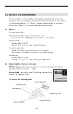
Page 19: ... number 420 88888 given on rear side of tension meter Standard rollers Model number R542017 Delivery 1 set 3 pcs of spare rollers 2000 m min To order ceramic pins Model ETPB 100 given on rear side of tension meter Serial number 420 88888 given on rear side of tension meter Ceramic pins Model number R542020 Delivery 1 set 3 pcs of spare ceramic pins 6000 m min 8 2 Replacing the rollers ceramic pins...

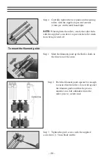
Page 20: ...llers Step 1 Loosen the rollers with the supplied open end wrench 4 mm jaw width NOTE Should any of the three threaded studs be damaged replace it by one of the threaded studs supplied with the new rollers Step 2 Screw off the rollers NOTE When loosening the rollers steady the roller bolts with the supplied screwdriver to prevent loosening of the roller shafts Step 3 Screw the new rollers to the r...

Page 21: ...ed screwdriver to prevent the roller shafts from being twisted off Step 1 Slide the filament guide up the Roller shafts in the direction of the arrow Step 3 Tighten the grub screws with the supplied screwdriver 1 5 mm blade width Step 2 Push the filament guide upward far enough to ensure that the rollers do not rub against the filament guide and that the process material can slide unhindered into ...

Page 22: ...x 1 KHz Sampling rate 200 Hz 2 Hz AVG MIN and MAX Display update rate 2 times per second Display Color TFT 128 x 160 Memory Average last value MAX MIN Communication frequency max 200 readings sec Temperature coefficient Gain less than 0 01 FS C Temperature range 10 45 C Air humidity 85 RH max Auto Power Off After approx 3 min of non use Power supply LiPo accumulator 20 h continouse use 3 hour char...

Page 23: ...r Material Standard 6000 Oxide ceramic Outer distance between outside guide rollers pins Suitable for 95 of all applications PA Polyamide Monofilament If the material to be measured differs significant from the factory calibration material in diameter rigidity shape etc we recommend calibration using customer supplied material For this purpose a material sample of about 5m should be supplied Inter...

Page 24: ...OR NATURE RESULTING FROM THE USE OF SUPPLIED EQUIPMENT WHETHER SUCH DAMAGE OCCURS OR IS DISCOVERED BEFORE UPON OR AFTER REPLACEMENT OR REPAIR AND WHETHER OR NOT SUCH DAMAGE IS CAUSED BY MANUFACTURER S OR SUPPLIER S NEGLIGENCE WITHIN ONE YEAR FROM INVOICE DATE Some State jurisdictions or States do not allow the exclusion or limitation of incidental or consequential damages so the above limitation m...

Page 25: ... 24 NOTES ...

Page 26: ......

Reviews: