36
36
■
■
■
■
■
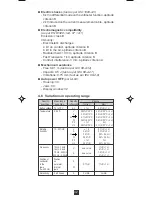
Active power measurement characteristics
Display range
4000 W
40 kW
400 kW
Measuring range
(2)
5 to
4.00 kW to
40.0 kW to
3999 W
39.99 kW
240.0 kW
(1)
Accuracy
(3)
2% R + 1 pt
Resolution
1 W
10 W
100 W
(
1) the scale is limited to 240 kW in one-phase (600 V x
400 A). Above this value, the display indicates +OL or
-OL depending on the sign of the power.
(2) if the power value is < 5 W or if the voltage
or current
values are respectively < 0.15 V or < 0.15 A, 0 is
displayed.
(3) The measurement accuracy is affected by an instability
linked to current measurement of approximately 0.1 A.
Example: for a power measurement performed at 10 A, the
instability of the measurement will be 0.1 A/10 A, or 1%.
■
■
■
■
■
MIN/ MAX Mode:
- Accuracy: same as previous table +0.3% R
- Capture time: 100 ms typ. (every 400 ms)
3.9 Power factor calculation (PF)
With the clamp configured in power measurement (switch on
position W) and correctly connected (see § 3.8), perform a
short press on the yellow key: the power factor is displayed.
The power factor is, by definition, an unsigned quantity, however,
a sign is displayed showing whether the charge is inductive
(“+” sign) or capacitive (“-” sign). This sign is significant only
in the case of slightly distorted signals (i.e. 3 switches to zero
over 1 period).
■
■
■
■
■
Characteristics
Display range
1.00
Measuring range
(1)
0.20 to
0.50 to
0.49
1.00
Accuracy
5% R
2% R
+ 2 pt
+ 2 pt
Resolution
0.01
(1)
The display of the power factor is limited to 1.00
If one of the terms of the power factor calculation is
outside its power range, the display of the power factor
indicates an indeterminate value”- - - -”.
■
■
■
■
■
MIN/ MAX Mode:
- Accuracy: Same for the table below + 1 pt
- Capture time: 100 ms typ. (every 400 ms)
3.10 Frequency Measurement (Hz)
This function is active for measurements V, A, W in AC.
For the power function, the frequency measurement is
performed on the voltage signal.


