


LiPo & LiFe, LiTo Battery Management System BMS24T V4.0
www.chargery.com
page 39 total 41
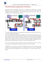
Supplemental, equipment voltage calibration
Various components such as Solar Charger Controllers, Inverter/Chargers need to "know" the precise voltages
being dealt with in regards to the batteries, with Lithium Based batteries, accurate voltage sensing is essential.
This is not a difficult process to do but as equipment varies a great deal on how they are configured and what
options they have, you will have to refer to the manuals for your particular equipment.
!
You will require an accurate DVOM (Digital Volt Ohm Meter) or DMM (Digital Multi-Meter) to
accomplish this task.
Simple Steps:
Do this when there is no charging from the Solar Charge Controller, best time to do this is just after sundown,
so that there is no solar activity.
1.
Ensure your batteries are charged and "at rest", meaning no loads or charging for 1 hour.
2.
The Solar Charge Controller, Inverter/Charger must connected and ON. As well, if you have a Buck
Converter / Step Down converter have that on BUT WITH NO LOAD being supplied to devices.
3.
First, take a Voltage Reading at the Battery Terminal (if only one pack) or at BUS Terminals if multiple
packs in parallel.
Test "after" the BMS but before the Relays as the BMS is on the "battery side". NOTE
the Voltage as ##.## volts (IE 28.92vdc or 14.86vdc)
4.
Next, measure the Voltage at the Inverter/Charger DC Input Terminals and again note it.
5.
Next measure the voltage at the Solar Charge Controller "Battery Terminals" (not the solar input
terminals) NB: The Solar Charge Controller should not be getting any sun, no input. NOTE the Voltage
seen at the Battery Terminals of the Controller.
6.
If you have an external AC to DC charger connected as well, check the voltage at the "terminals" of
the charger and note them as well.
You will now see a difference in readings between the Batteries, the Solar Charge Controller & the Inverter
Charger. This is the result of "deration", essentially the wire and every single connector in between adds a bit
of loss through the whole circuit and this must be addressed.
! ALERT !
If the discrepancy is more than 1
Volt you may have other problems, such as a loose connection, poor crimps or damaged wire /
components. This must be addressed first and once done, redo above readings.
The BATTERY reading
(be it a single or a bank of packs) is the one that RULES and the remaining equipment must "match up" to be
effective.
Example using basic numbers to Keep It Simple:
Assume the Battery reads 24.0 VDC, the Solar Charge Controller reads 23.75 VDC and the Inverter/Charger
reads 23.60 VDC.
EXAMPLE:
If the desired CHARGING cutoff is 29.20 VDC, then the SCC would have to be corrected for the
0.25V shortfall in readings, so it would be programmed to cutoff at 29.45 VDC. The Inverter Charger "Charge
cutoff" would then also have to be corrected to 29.60 VDC to compensate for the 0.40 VDC difference.
LOW Volt Disconnect !
The Inverter will have it's own LVD (Low Voltage Disconnect) setting and this is extremely important. While
0.40V is not a big difference, it can be if you want to keep within a very specific range and with Lithium based
batteries 0.40V at the bottom edge
can be significant !
So you would have to Correct the voltage the
Inverter/Charger sees, so that it cuts off exactly at the voltage desired "at the battery terminal end". So IF
you want the LVD to kick on when the cells reach 2.75VDC ea / 22.0 VDC for the 24V pack/bank, the LVD
setting will have to be adjusted to 22.40. This way when the Inverter/Charger sees 22.40 Volts it cuts off as
the actual batteries are at 22.0VDC. 21.60 VDC = 2.70v per cell.(uncorrected) * REMEMBER, that below


