


LiPo & LiFe, LiTo Battery Management System BMS24T V4.0
www.chargery.com
page 37 total 41
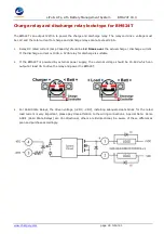
c)
The STOP button will NOT stop an Inverter while drawing power and will NOT stop charging if there is
current from the Charger. Loads & Charger must be OFF to allow the BMS to enter into Sleep Mode.
8.
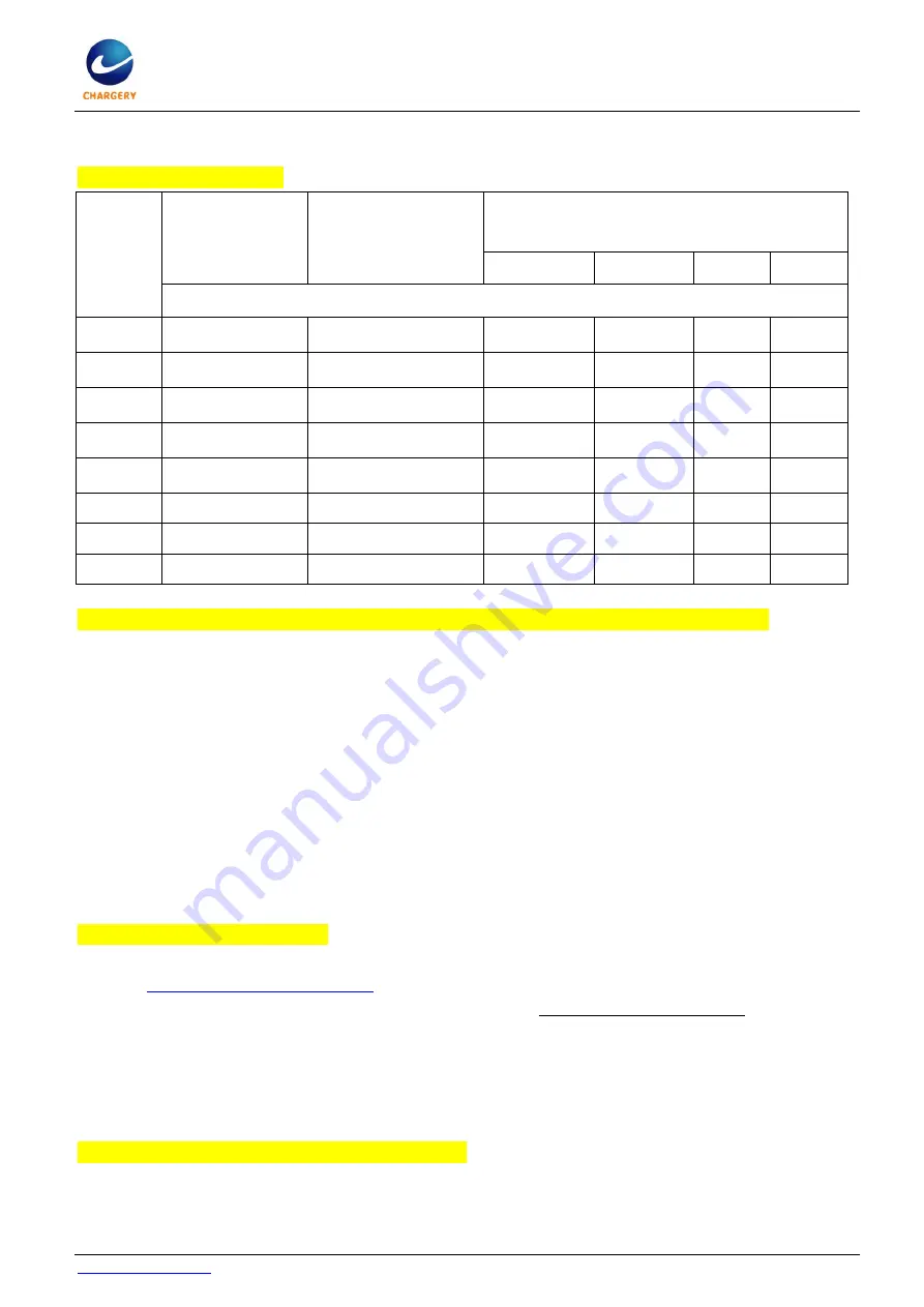
BMS power consumption
Battery
voltage
Normal mode
without Relay
but LCD is on
Sleep mode
without relay and
LCD is off
Normal mode with 12V mechanical relay
with different rated current and LCD is on
100A
200A
400A
600A
BMS drain current from battery (mA)
16V
120
40
500
850
1150
1425
24V
84.25
35
475
550
725
890
36V
65
50
325
365
485
587.5
48V
55
42.5
247.5
280
370
445
60V
48.75
29
207.5
230
302.5
365
67.2V
46
28.25
187.5
207.5
275
332.5
84V
40
27
150
170
222.5 266.25
96V
38.5
26.25
135
150
200
235
9.
BMS Relay controller output current at 12V when Chargery Mechanical Relay closed.
a)
12V 100A relay, coil current is 0.75A at 12V drive voltage.
b)
12V 200A relay, coil current is 0.96A at 12V drive voltage.
c)
12V 400A relay, coil current is 1.24A at 12V drive voltage.
d)
12V 600A relay, coil current is 1.3A at 12V drive voltage.
Because the relay coil current is far more than BMS working current, to avoid any cell being over
discharged, please operate as below,
a)
if the battery is not in use (exclude charging), please disconnect coil driven wire.
b)
If storage for over 1 month, please press STOP button place the BMS into Sleep Mode.
c)
If storage for over 3 months, please turn off the BMS directly. You may use the External / Internal
power switch if using internal power.
10.
Show timeout during updating,
a)
Download the correct firmware according to product model and save to your PC, from
http://chargery.com/update.asp
b)
Update tool software version must be v1.03 or greater. Always use the most current.
c)
Connect BMS main unit or LCD unit to the PC by using the provided USB cable.
d)
Turn on BMS main unit.
e)
Execute update tool software and lock the com port by click OPEN button.
f)
Click open file button and upload the correct firmware.
g)
Click update button finish update.
11.
Charging stops, the possible reasons are as below.
a)
Any cell voltage reaches “Over Charge Protection(P) Voltage“ setting.
b)
The highest cell voltage is over “Over Charge Release(R) Voltage” setting.
c)
Charging current is over “Over charge current” setting.


