


LiPo & LiFe, LiTo Battery Management System BMS24T V4.0
www.chargery.com
page 26 total 41
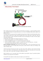
Relay Delay Time Board
When a Motor and many Inverters are started, the initial surge is very large. In order to restrict the current
surge, CHARGERY designed this special delay board, it can work with CHARGERY BMS8T, BMS16, BMS16T and
BMS24T and so on.
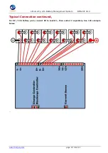
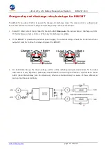
The board receives the relay signal from the BMS, the Charge Relay and Small Current Discharge Relay will be
closed without a delay. But the Large Current Discharge Relay will be closed after a delay time. When the
Large Current Relay is closed, the Small Current Relay will open automatically according to the below jumper
connections diagram below:
The delay time can be adjusted by changing the jumpers J1, J2 and J3.
2.
Short circuit ALL jumpers: J1, J2 and J3, the delay time = 2 seconds,
3.
Short circuit ONE of 3 jumpers”: J1, or J2 or J3, the delay time = 6 seconds.
4.
Short circuit TWO of 3 jumpers: J1 and J2, or J2 and J3, or J1 and J3, the delay time = 3 seconds.
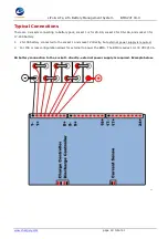
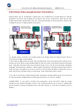
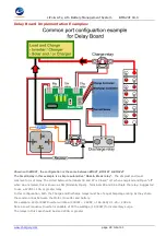
The small current relay and large current connection is as below,
Before completing connections:
please power off the switcher (LED 1 is off). On the board, there are two
BLUE LED indicators, when the Charge relay is closed, LED 2 is ON, otherwise it is OFF, when Discharge relay
closed, the LED 1 is ON.
Finish all connection and setup, when ready to go, please close all other switchers on other device first, finally
power on the switcher on the board, LED 1 is ON, small current relay closed immediately, after setup delay
time, the large current relay closed. The battery will discharge normally.
When the battery is not in use, please power off the switcher to save battery energy. The switcher should be
installed on convenient place to be operated.
The large NTC Power Resistors must be chosen by delay time and load current.


