background image

Water Connections (cont’d)

4.

A 3/4" Pressure Regulating Valve (PRV), should be installed on the incoming water supply
line if water flow pressure exceeds 20-22 psi/138 Kpa. 
A PRV is standard equipment on Model D-HB.
A PRV is not standard equipment on Models D-H1 and D-LF.
The PRV may be obtained locally or direct from Champion. 

Drain Connections

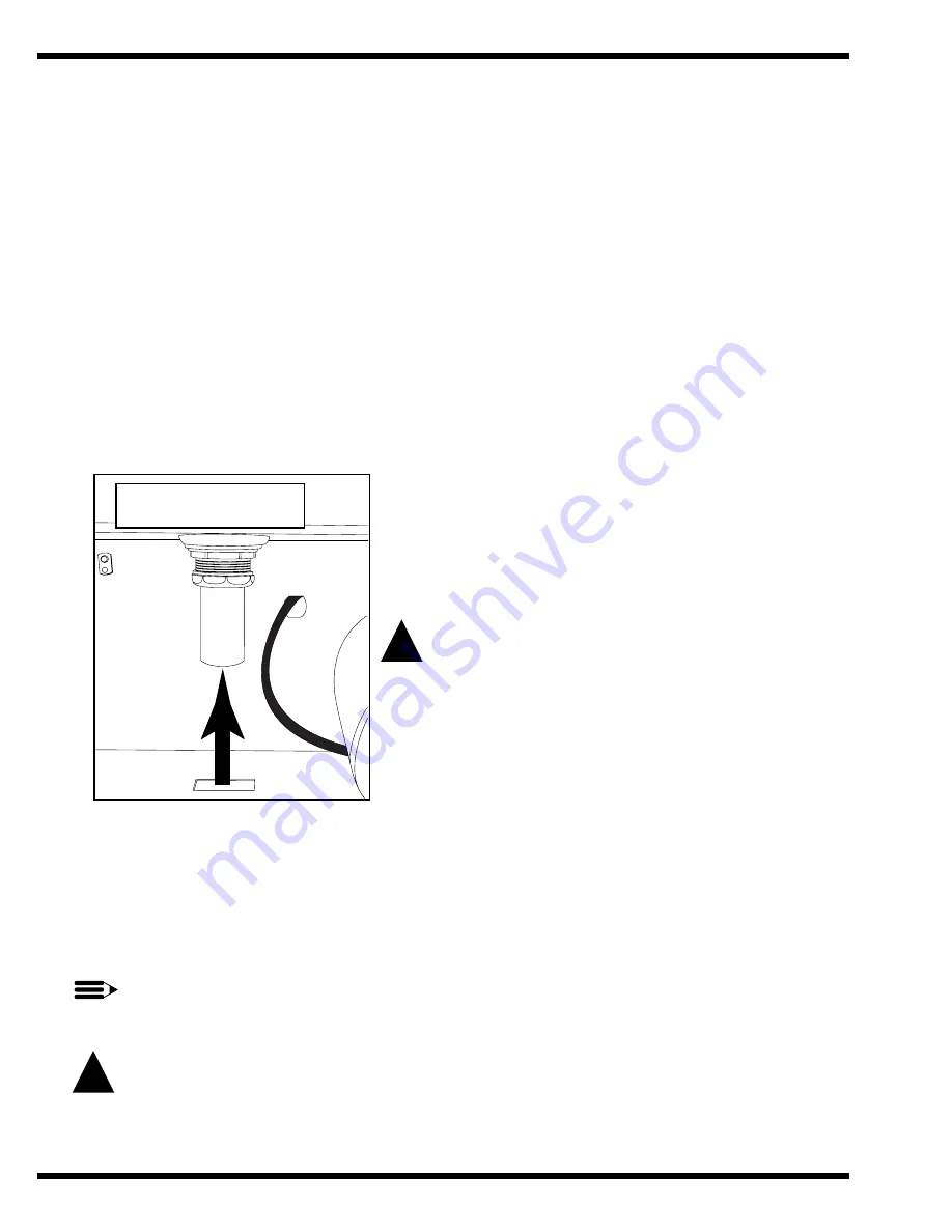
Refer to Fig. 5 for the location of the machine drain.

1.

Models D-HB, D-H1, and D-LF are GRAVITY DRAIN machines equipped 
with a 1-1/2" hose connection point. 
• Drain height for ALL MODELS must not exceed 11" [280mm] above floor level.

WARNING:

Connection of the machine to a drain line 
higher than the machine drain height
will prevent the machine from draining properly.

Ventilation

NOTE:

Ventilation must comply with local sanitary and plumbing codes. 

CAUTION:

Exhaust air should not be vented into a wall, ceiling, or concealed space of a building. 
Condensation can cause damage. 

12

INSTALLATION

!

Figure 5

D-HB, D-H1, D-LF

1-1/2" Drain Connection

Lower Center of Machine

1-1/2" Drain Connection

11” [280mm] above floor level

!

Summary of Contents for D-H1M3

Page 1: ...w Temperature June 1998 P O Box 4149 Winston Salem North Carolina 27115 4149 336 661 1556 Fax 336 661 1660 Email champion championindustries com Manual P N 112428 Rev A Champion Machine Serial No Champion Industries Inc 2674 N Service Road Jordan Station Ontario Canada L0R 1S0 905 562 4195 Fax 905 562 4618 For machines beginning with serial no 90343 and above ...

Page 2: ... Champion Service Agency____________________________________ Phone ______________ ______________________________________________________________________________ Champion Industries Service 1 800 858 4477 Champion Service Fax 1 336 661 1660 In Canada Champion Service 1 800 263 5798 Canada Service Fax 1 905 562 4618 We strongly recommend that you fax your orders NOTE When calling to order parts be s...

Page 3: ...al Number Comments Date Pages Effectivity 10 6 97 All 90343 Issue manual with replacement parts lists 4 23 98 43 91586 Redesigned overflow lift arm P N 112469 order P N s 112469 S and 322218 for machines built prior to S N 91586 1 REVISIONS ...

Page 4: ...ns 11 Drain Connections 12 Chemical Connections 13 Model D HB D H1 and D LF 13 Detergent 13 Rinse Aid Sanitizer 14 INITIAL START UP 16 Model D HB D H1 and D LF OPERATION 17 Model D HB D H1 and D LF MAINTENANCE 18 Maintenance Schedule 18 CLEANING 18 Every 2 Hours or After Each Meal Period Model D HB D H1 and D LF 18 Every 8 Hours or at the End of the Day Model D HB D H1 and D LF 18 DELIMING 19 Deli...

Page 5: ...igure 5 Drain Connection 12 Figure 6 Chemical Connection Points 13 Figure 7 Wash Tank Detergent Equipment Insertion Points 13 Figure 8 Rinse Aid Injection Point D HB D H1 Only 14 Figure 9 Rinse Aid Sanitizer Injection Points D LF 15 Figure 10 Operator Controls 16 Figure 11 Door Activated Drain Lever Assembly 16 Figure 12 Fuses 23 Figure 13 Motor Overload 23 Figure 14 Cycle Timer 24 Figure 15 Cycle...

Page 6: ...tric Booster and Thermostat D HB Only 46 Figure 31 D HB Lower Fill Piping Assembly 48 Figure 32 D HB D H1 Upper Fill Piping Assembly 50 Figure 33 D H1 D LF Lower Fill Piping Assembly 52 Figure 34 D LF Upper Fill Piping Assembly 54 Figure 35 Pump Assembly 56 Figure 36 Control Cabinet 58 Figure 37 Dishracks and PRV 60 Figure 38 Electrical Schematic D HB D H1 D LF 3 Phase 64 Figure 39 Electrical Sche...

Page 7: ...t of clutches f Opening or closing of utility supply valves or switching of electrical supply current g Cleaning of valves strainers screens nozzles or spray pipes h Performance of regular maintenance and cleaning as outlined in operator s guide i Damages resulting from water conditions accidents alterations improper use abuse tampering improper installation or failure to follow maintenance and op...

Page 8: ... within ten 10 days after the installation of your machine All information illustrations and specifications contained in this manual are based upon the latest product information available at the time of publication Champion constantly improves its products and reserves the right to make changes at any time or to change specifications or design without notice and without incurring obligation For y...

Page 9: ...n electric D HB only or Two dish racks peg and flat bottom steam booster heater D HB only Detergent chemical connection provisions Door activated drain Stainless steel front and side panels Field convertible to corner model Top mounted splash proof control console Electric tank heat 60 second time cycle Balanced three door lift system 1 1 2 O D gravity drain connection Low water tank heat protecti...

Page 10: ...D HB 220 60 1 40 F 23 C 61 Amps 76 Amps D HB 230 60 1 40 F 23 C 63 Amps 79 Amps D HB 240 60 1 40 F 23 C 65 Amps 81 Amps D HB 208 60 3 40 F 23 C 33 Amps 41 Amps D HB 220 60 3 40 F 23 C 35 Amps 44 Amps D HB 230 60 3 40 F 23 C 36 Amps 45 Amps D HB 240 60 3 40 F 23 C 37 Amps 46 Amps D HB 380 60 3 40 F 23 C 20 Amps 25 Amps D HB 415 60 3 40 F 23 C 20 Amps 25 Amps D HB 480 60 3 40 F 23 C 17 Amps 21 Amps ...

Page 11: ...ssure gauge in the upper fill piping of the dishwasher in the petcock provided NOTE The installation of your machine must meet local health codes Changing from Straight through to Corner Operation Your door type dishwasher is shipped from the factory in a straight through configuration The following instructions explain how to convert your machine for corner operation Refer to Fig 1 below 1 Place ...

Page 12: ...work is being done on that circuit 1 A qualified electrician must compare the electrical power supply with the machine electrical specifications stamped on the MACHINE ELECTRICAL CONNECTION PLATE located inside the top mounted control cabinet before connecting to the incoming service at a fused disconnect switch 2 Motor rotation was set at the factory Check the rotation of the motor shaft CW when ...

Page 13: ...temperature requirements are listed below D HB with built in 40 F 23 C rise electric booster Minimum 140 F 60 C Min Max flow pressure 20 22 psi 138 Kpa D HB with built in 70 F 39 C rise electric booster Minimum 110 F 43 C Min Max flow pressure 20 22 psi 138 Kpa D H1 without built in booster Minimum 180 F 70 C Min Max flow pressure 20 22 psi 138 Kpa D LF Minimum 120 F 49 C 140 F 60 C Optimum Min Ma...

Page 14: ...F are GRAVITY DRAIN machines equipped with a 1 1 2 hose connection point Drain height for ALL MODELS must not exceed 11 280mm above floor level WARNING Connection of the machine to a drain line higher than the machine drain height will prevent the machine from draining properly Ventilation NOTE Ventilation must comply with local sanitary and plumbing codes CAUTION Exhaust air should not be vented ...

Page 15: ...tergent equipment insertion points 13 INSTALLATION 10 15 2 2 19 18 17 12 6 5 CAUTION 120V SUPPLY DISPENSERS ONLY RINSE SANI DETERGENT COMMON RETURN Figure 6 D HB D H1 D LF Chemical Connection Points Left Side Interior of Control Cabinet Signal connection points include Detergent signal 120VAC between Wire 10 and Wire 2 1 AMP MAX AMP LOAD Rinse Aid Sanitizer signal 120VAC between Wire 15 and Wire 2...

Page 16: ...g 8 1 A rinse aid injection point is provided via a 1 4 NPT plug located in the final rinse piping The plug is located in a cross fitting on the outlet side of the vacuum breaker The vacuum breaker is located behind the control cabinet at the top of the machine 2 Use a liquid rinse aid NOTE Models D HB and D H1 do not require sanitizer 14 INSTALLATION Figure 8 Rinse aid Insertion Point D HB D H1 O...

Page 17: ...the outlet side of the vacuum breaker The vacuum breaker is located behind the control cabinet at the top of the machine 4 Use a sodium hypochlorite Chlorine based sanitizer at a minimum concentration of 50PPM in the final rinse Use chlorine test papers to verify and monitor the 50PPM chlorine level WARNING Never premix rinse aid with the sanitizing agent Mixing may cause hazardous gases to form C...

Page 18: ... the machine will automatically fill with water 6 Check the machine for leaks 7 Push the Green Start Button to check automatic cycle 8 Check pump motor rotation Rotation is CW when viewed from rear of motor 9 If machine checks okay lift the drain lever assembly to drain machine 10 Flip the power switch to OFF 16 INITIAL START UP WASH RINSE Champion ON OFF TURN OFF POWER BEFORE SERVICING MACHINE W ...

Page 19: ...ins Machine washes for 45 sec then pauses for 1 sec 6 During Final Rinse monitor pressure Machine final rinses for 14 sec Pressure gauge and final rinse temperature gauge reading must read between 20 22 PSI gauge Temperature gauge must read 180 195 F 82 91 C D HB D H1 Only Min 120 140 F 49 C 60 C Optimum D LF Only 7 60 second cycle complete Green cycle light goes out 8 Open door remove clean rack ...

Page 20: ...th fresh water 4 Remove and clean the scrap screens Clean the pump intake screen 5 Inspect the spray arm nozzles and rinse nozzles Clean if necessary 6 Close door flip power switch ON to refill machine Every 8 Hours or at the End of the Day Model D HB D H1 and D LF 1 Flip the power switch OFF 2 Lift drain lever drain the machine 3 Flush tank interior with fresh water 4 Remove and clean the scrap s...

Page 21: ...om machine 2 Remove any chemical pick up tubes from their containers 3 Place each tube in a container of fresh water and prime the chemical lines for several minutes to thoroughly flush chemical from the lines Leave pick up tubes out of their containers 4 Drain the machine and refill with fresh water 5 Spray interior walls with delimimg solution and let sit for 5 or 10 minutes depending on amount ...

Page 22: ...er detergent and rinse additive dispensers are adequately filled If a problem still exists use the following for troubleshooting CONDITION CAUSE SOLUTION Machine will not start Door not closed Make sure doors are fully closed Door safety switch faulty Contact your service agency Start switch faulty Contact your service agency Main switch OFF Check disconnect Overload protector tripped Reset overlo...

Page 23: ... pressure reducing valve Set psi flow pressure at 20 22 psi 138 Kpa Clogged rinse nozzle and or pipe Clean Improper water line size Have installer change to proper size 3 4 min Clogged Y strainer Clean or replace Low final rinse temperature Low incoming water temperature Check house supply water temperature Improper setting of booster thermostat Be sure booster thermostat is set to maintain 180 F ...

Page 24: ...ROUND WHEN PERFORMING VOLTAGE CHECKS Doing so will result in false and inaccurate readings PERFORM VOLTAGE CHECKS BY READING FROM THE HOT SIDE OF THE LINE AND NEUTRAL any 2 or white wire WARNING USE EXTREME CAUTION when performing tests on energized circuits WARNING When repairing a circuit disconnect the power at the main service disconnect switch and place a tag at the disconnect switch to indic...

Page 25: ...e electrical overloads The overload disconnects 120VAC power to the motor contactor coil Refer to Fig 13 Note the Switch Lever on the Overload If the switch lever is off with the 0 showing then the overload has tripped To Reset the Motor Overload Flip the overload switch to the On position A 1 should be visible on the switch lever To Replace a Motor Overload Disconnect the wires to the overload Re...

Page 26: ...mer consists of a timer motor one micro switch and one non adjustable plastic cam The fill timer operates during initial fill and any time the low water tank heat protection circuit calls for make up water Refer to Timed Fill Low Water Tank Heat Protection on the next page for an explanation of the fill timer operation ELECTRICAL SERVICE cont d Timed Fill Low Water Tank Heat Protection 24 BASIC SE...

Page 27: ...at switch ball moves down heat de energizes The fill solenoid energizes and the fill timer runs for a minimum of 90 seconds to refill the tank 4 If the tank is not full of water at the end of the 90 second fill timer cycle then the fill timer will cycle again When the float switch is satisfied the fill timer stops after completing its 90 sec cycle 5 Refer to the float switch troubleshooting chart ...

Page 28: ... Configuration B Booster tank element View of calrod coils Terminal Connections view of element Configuration C Booster tank element View of calrod coils Terminal Connections view of element Configuration D Wash tank element View of calrod coils Terminal Connections view of element 208V 1 Phase 208 240V 3 Phase Delta Connection 480V 3 Phase 575V 3 Phase Delta Connection 208 240V 3 Phase Wye Connec...

Page 29: ...n block For single phase machines motor rotation is changed at the motor connection plate on the rear of the single phase motor If necessary Refer to Fig 20 for the proper wiring of the pump motor for single and three phase voltages 27 BASIC SERVICE Three Phase High Voltage L1 L2 4 2 8 J LINE LINE 3 Figure 20 Pump Motor Wiring Diagrams 6 5 4 9 8 7 3 2 1 LINE 6 5 4 9 8 7 3 2 1 LINE 3 2 1 LINE 2 8 J...

Page 30: ...seat in the pump flange and clean thoroughly 13 Press rubber seal ceramic portion of seal assembly into the pump flange Use a water soluble lubricant Be careful to keep the ceramic clean 14 Install the rotating part of the seal on the shaft with the graphite surface toward the ceramic Use a water soluble lubricant on the rubber seal part only not the graphite 15 Reinstall impeller and new flange g...

Page 31: ...29 REPLACEMENT PARTS REPLACEMENT PARTS ...

Page 32: ...30 REPLACEMENT PARTS Figure 22 D HB D H1 D LF Doors Panels and Gauges 13 11 8 4 4 25 26 26 26 7 12 23 24 13 14 15 16 17 18 19 20 21 22 1 2 3 6 4 7 9 5 10 8 9 ...

Page 33: ...SST 1 12 108954 NUT GRIP 6 32 W NYLON INSERT 2 13 100007 SCREW 10 32 X 3 8 TRUSS HEAD 2 14 0508752 SCREW 4 40 X 5 8 ROUND HEAD 2 15 0508668 DECAL CONTROL CABINET 1 16 108391 THERMOMETER 4FT FINAL RINSE 1 17 112090 OVERLAY FINAL RINSE 180 195 F 1 112092 OVERLAY FINAL RINSE 120 F D LF ONLY 1 18 107440 THERMOMETER 8FT WASH 1 19 112086 OVERLAY WASH 150 F 1 112093 OVERLAY WASH 120 F D LF ONLY 1 20 3054...

Page 34: ...32 REPLACEMENT PARTS Figure 23 D HB D H1 D LF Door Guides Stops and Lift Bracket 8 2 9 4 3 2 2 1 5 6 7 ...

Page 35: ...Description Qty 1 108053 PLUG CORNERPOST 2 2 107966 NUT GRIP 10 32 W INSERT 8 3 0309277 BRACKET DOOR LIFT 1 4 100097 SCREW 10 32 X 1 2 TRUSS HEAD 2 5 108347 GUIDE DOOR 6 6 108410 GASKET DOOR GUIDE 26 12 7 107970 SCREW 8 32 X 1 FILISTER 36 8 100007 SCREW 10 32 X 3 8 TRUSS HEAD 2 9 0307328 STOP DOOR 2 ...

Page 36: ...MENT PARTS Figure 24 D HB D H1 D LF Door Handle and Spring Assembly 1 2 2 3 3 4 5 6 6 7 7 9 9 8 8 5 1 10 10 14 15 16 17 18 18 19 20 21 20 22 23 13 10 14 13 10 11 11 11 11 12 12 24 25 25 26 26 26 27 24 24 26 27 24 ...

Page 37: ...107420 NUT PLAIN M6 8 11 107436 SCREW M6 X 16MM FILISTER 6 12 107399 SUPPORT PIVOT BLOCK 2 13 304811 GASKET BACKING 2 14 108368 PLATE BACKING 2 15 100740 BOLT 5 16 18 X 1 HEX HEAD 2 16 107966 NUT GRIP 10 32 W NYLON INSERT 8 17 322077 GUARD SPLASH 2 18 100097 SCREW 10 32 X 1 2 TRUSSHEAD 8 19 0509264 BUSHING SIDE DOOR 2 20 0509274 NUT ACORN 5 16 18 SST 2 21 0309167 LIFT BAR DOOR 2 22 102376 WASHER F...

Page 38: ...36 REPLACEMENT PARTS Figure 25 D HB D H1 D LF Track Assembly 6 2 6 8 1 6 8 7 11 5 11 7 8 7 7 7 10 9 4 6 6 6 7 10 9 8 3 10 9 10 9 ...

Page 39: ...Guide right hand 1 2 0309472 Track rear 1 3 0309468 Guide left hand 1 4 0309470 Support rack 1 5 0309471 Track front 1 6 106727 Screw 10 32 x 5 8 Flat Hd 6 7 107966 Nut grip 10 32 w nylon insert 6 8 100779 Bolt 1 4 20 x 5 8 Truss Hd 8 9 106482 Washer lock 8 10 100003 Nut 1 4 20 Hex Hd 8 11 0309473 Spacer 2 ...

Page 40: ...38 REPLACEMENT PARTS Figure 26 D HB D H1 D LF Wash Rinse Spray Piping FRONT LEFT SIDE 6 4 14 5 4 3 2 1 13 12 11 10 12 11 12 8 7 8 9 2 ...

Page 41: ...509150 CONNECTOR TOP RINSE 1 4 0509180 FITTING STRAIGHT COMPRESSION 2 5 0309445 RINSE TUBE TOP 1 6 0509179 FITTING BULKHEAD 1 2 NPT 1 7 0507445 SPINDLE WASH ARM 2 8 109864 SUPPORT WASH ARM 2 9 0509178 CONNECTOR BOTTOM RINSE 1 10 109781 STANDPIPE WASH 1 11 100736 BOLT 1 4 20 X 3 4 HEX HEAD 2 12 107967 NUT GRIP 1 4 20 1 13 106482 WASHER SPLIT LOCK SST 2 14 0309350 WASHER 1 ...

Page 42: ...40 REPLACEMENT PARTS Figure 27 D HB D H1 D LF Wash Rinse Spray Arms 9 2 9 2 4 1 3 3 6 5 7 8 10 ...

Page 43: ... BEARING RINSE ARM 4 4 0707453 RINSE ARM ASSY Includes 2 3 2 5 0507444 NUT RINSE ARM 2 6 109835 SCREW 8 X 1 2 PAN HD 4 7 0707452 S WASH ARM ASSY Includes 6 8 2 8 0507446 BEARING WASH ARM 2 9 0507451 NOZZLE RINSE ARM SST Model D LF only 12 10 0708899 RINSE ARM ASSY Model D LF only Includes 3 9 1 0707450 RINSE ARM Does not include items 2 3 or 9 0707456 WASH ARM Does not include item 8 ...

Page 44: ...42 REPLACEMENT PARTS Figure 28 D HB D H1 D LF Drain Assembly and Scrap Screens 14 15 11 12 16 20 21 17 18 19 13 10 5 4 8 7 6 5 4 1 2 9 3 4 4 4 6 6 ...

Page 45: ...03 NUT PLAIN 1 4 20 SST 9 5 106482 WASHER LOCK 1 4 SPLIT 3 6 106026 WASHER 1 4 X 5 8 X 1 16 SST 3 7 111391 LIFT ARM SPRING 1 8 102376 WASHER 5 16 X 3 4 X 1 16 2 9 322217 ACTUATOR MOUNTING BRACKET 1 10 112463 ACTUATOR KEEPER PLATE 1 11 322218 ACTUATOR 1 12 112462 OVERFLOW ACTUATOR GUIDE 1 13 322216 LH FILLER PLATE 1 14 305164 SCREEN SCRAP 10 3 8 2 15 322215 CENTER SCREEN FILLER PLATE 1 16 205813 DR...

Page 46: ...44 REPLACEMENT PARTS Figure 29 D HB D H1 D LF Wash Tank Heat Thermostats and Float Switch Thermostat bracket detail 1 2 3 4 6 5 5 7 7 8 9 10 11 12 13 14 15 16 17 17 18 19 18 19 ...

Page 47: ...1151 C CLIP FLOAT SWITCH 2 10 100740 BOLT 5 16 18 X 1 HEX HEAD 4 11 108345 GASKET 3 X 3 X 1 8 2 1 12 102376 WASHER 5 16 X 3 4 X 1 16 8 13 106013 WASHER LOCK 5 16 SPLIT 4 14 100154 NUT PLAIN 5 16 18 SST 4 15 0509637 HEATER 3KW 115V 1PH 1 0509185 HEATER 3KW 208 240 380 415V 1 3PH 1 0509373 HEATER 3KW 460V 3PH 1 0507707 HEATER 3KW 575V 3PH 1 16 100007 SCREW 10 32 X 3 8 TRUSS HEAD 4 17 107966 NUT GRIP...

Page 48: ...46 REPLACEMENT PARTS Figure 30 D HB Only Electric Booster and Thermostat T O U P P E R P I P I N G F R O M F I L L V A L V E 5 3 4 6 7 8 9 10 11 12 1 1 2 2 ...

Page 49: ...R 5 109069 THERMOSTAT BOOSTER 1 6 100003 NUT PLAIN 1 4 20 SST 3 7 106482 WASHER LOCK 1 4 SPLIT 3 8 111233 HEATER 9KW 208 240 380 415V 40 Rise 1 3 phase 1 108579 HEATER 9KW 480V 40 Rise 3 phase only 1 111122 HEATER 9KW 575V 40 Rise 3 phase only 1 9 111266 HEATER 18KW 208 240 380 415V 70 Rise 1 3 phase 1 111267 HEATER 18KW 480V 70 Rise 3 phase only 1 111600 HEATER 18KW 575V 70 Rise 3 phase only 1 10...

Page 50: ...48 REPLACEMENT PARTS Figure 31 D HB ONLY Lower Fill Piping Assembly CUSTOMER WATER INLET TO UPPER PIPING 2 8 6 5 5 4 3 2 9 5 7 1 10 11 ...

Page 51: ...102444 STREET ELL 3 4 NPT BRASS 2 3 102651 NIPPLE 3 4 x 2 BRASS 1 4 111437 VALVE 3 4 NPT HOT WATER 1 5 100184 NIPPLE 3 4 NPT 3 6 102442 ELBOW 3 4 NPT X 90 1 7 100571 UNION 3 4 NPT BRASS 1 8 109879 COMPRESSION FITTING 3 4 X 7 8 1 9 205761 3 4 COPPER TUBE FORMED 1 10 108516 COIL SOLENOID VALVE 120v 1 11 109903 REPAIR KIT 3 4 SOLENOID VALVE 1 ...

Page 52: ...50 REPLACEMENT PARTS Figure 32 D HB D H1 Upper Fill Piping Assembly 1 3 4 5 6 3 7 8 9 10 11 FINAL RINSE THERMOMETER BULB WATER IN FROM LOWER PIPING 7 12 13 2 14 14 15 ...

Page 53: ... NPT BRASS 1 5 108181 BUSHING RED 3 4 X 1 4 NPT PLASTIC 1 6 107463 PLUG 1 4 NPT PLASTIC 1 7 100184 NIPPLE 3 4 NPT CLOSE BRASS 2 8 102525 TEE 3 4 X 1 2 X 3 4 NPT BRASS 2 9 102388 BUSHING RED 1 2 NPT X 1 4 NPT 1 10 112437 NEEDLE VALVE 1 4 NPT BRASS 1 11 100135 PRESSURE GAUGE 0 60PSI 1 12 104429 VACUUM BREAKER 3 4 NPT BRASS 1 13 109879 COMPRESS FITTING 3 4NPT X 7 8OD 1 14 100209 NIPPLE 1 2 NPT BRASS ...

Page 54: ...52 REPLACEMENT PARTS Figure 33 D H1 D LF Lower Fill Piping Assembly 6 6 TO UPPER PIPING 9 5 4 2 1 3 CUSTOMER WATER IN 5 7 8 1 10 11 ...

Page 55: ...ING SUPPORT BRACKET 1 3 110768 LINE STRAINER 3 4 BRASS 1 4 111437 VALVE 3 4 NPT HOT WATER 1 5 100184 NIPPLE 3 4 NPT CLOSE BRASS 2 6 102442 ELBOW 3 4 NPT BRASS 2 7 109879 COMPRESSION FITTING 3 4 NPT X 7 8 1 8 102470 NIPPLE 3 4 NPT X 3 BRASS 1 9 205761 TUBE 3 4 COPPER FORMED 1 10 108516 COIL SOLENOID VALVE 120v 1 11 109903 REPAIR KIT 3 4 SOLENOID VALVE 1 ...

Page 56: ...54 REPLACEMENT PARTS Figure 34 D LF Upper Fill Piping Assembly 1 2 3 4 14 5 6 3 7 8 9 10 11 FINAL RINSE THERMOMETER BULB WATER IN FROM LOWER PIPING 7 12 13 15 15 16 ...

Page 57: ...08181 BUSHING RED 3 4 X 1 4 NPT PLASTIC 1 6 107463 PLUG 1 4 NPT PLASTIC 1 7 100184 NIPPLE 3 4 NPT CLOSE BRASS 2 8 102525 TEE 3 4 X 1 2 X 3 4 NPT BRASS 2 9 102388 BUSHING RED 1 2 NPT X 1 4 NPT 1 10 112437 NEEDLE VALVE 1 4 NPT BRASS 1 11 100135 PRESSURE GAUGE 0 60PSI 1 12 104429 VACUUM BREAKER 3 4 NPT BRASS 1 13 109879 COMPRESS FITTING 3 4 NPT X 7 8OD 1 14 107424 PLUG 1 8 NPT PLASTIC 1 15 100209 NIP...

Page 58: ...56 REPLACEMENT PARTS Figure 35 D HB D H1 D LF Pump Assembly 1 2 3 7 4 6 5 8 9 10 11 12 13 15 16 17 18 19 20 21 22 23 24 27 26 28 29 30 31 25 14 ...

Page 59: ...1 18 111111 PUMP SEAL 1 19 109649 BACK PUMP HOUSING 1 20 107690 NUT JAM 3 8 16 4 21 106407 WASHER LOCK 3 8 SPLIT 4 22 204460 BACKING PLATE MACHINED 1 23 109654 PUMP SLINGER WASHER 1 24 110734 STUD 3 8 16 X 1 3 8 4 25 111145 MOTOR 1 4HP 208 240V 460V 60 3 1 111144 MOTOR 1 4HP 115V 208 240V 60 1 1 0507708 MOTOR 1 4HP 575V 60V3PH 1 26 100739 BOLT 5 16 18 X 3 4 HEX HEAD 4 27 102376 WASHER FLAT 5 16 4 ...

Page 60: ...1 12 14 13 15 10 1 18 9 22 2 8 23 24 BOOSTER CONTACTOR TANK HEAT CONTACTOR WASH MOTOR CONTACTOR WASH MOTOR OVERLOAD TRANSFORMER LINE V 120V 20 21 TRANSFORMER 120V 24V 17 16 WASH RINSE Champion ON OFF TURN OFF POWER BEFORE SERVICING MACHINE W A R N I N G IN CYCLE POWER START 25 ...

Page 61: ...1464 Transformer control 380 415V 3PH 1 7 111521 Transformer control 575V 3PH 1 8 111090 Reed switch magnetic 1 9 0508895 Terminal block 1 10 0508469 Timer fill assembly 1 11 106402 Fuse block 2 Pole 1 3 Phase 1 12 107289 Fuse 2 5A 208 240V 1PH 2 12 107289 Fuse 2 5A 208 240V 3PH 2 12 0508707 Fuse 1A 380 415V 3PH 2 12 0508707 Fuse 1A 480V 3PH 2 12 0508708 Fuse 2 5A 575V 3PH 2 13 106925 Fuse block 3...

Page 62: ...1 2 3 60 REPLACEMENT PARTS Figure 37 D HB D H1 D LF Dishracks and PRV ...

Page 63: ...61 REPLACEMENT PARTS D HB D H1 D LF DISHRACKS AND PRV Fig 37 Part Item No No Part Description Qty 1 101273 RACK FLAT BOTTOM 1 2 101285 RACK PEG 1 3 112387 PRESSURE REDUCING VALVE 3 4 PRV A R ...

Page 64: ...62 REPLACEMENT PARTS THIS PAGE INTENTIONALLY LEFT BLANK ...

Page 65: ...63 ELECTRICAL SCHEMATICS ELECTRICAL SCHEMATICS ...

Page 66: ...2 2 4 LT1 WHITE 27 230V 208V 115V H4 H3 H2 H1 X2 X1 3A CB 380V NC NO NC NO NO NC NC NO 415V 575V 208 230 480 575 VAC 380 415 VAC 208 230 VAC 380 415 575 VAC NC NO 480 L3 L2 L1 701046 REV E WV WASH TANK STEAM VALVE TS6 BOOSTER SAFTEY THERMOSTAT TS4 BOOSTER THERMOSTAT STEAM TS3 WASH THERMOSTAT STEAM TS2 BOOSTER THERMOSTAT TS1 WASH THERMOSTAT TRA D TIMER CAM SWITCHES TR TIMER MOTOR T1 CONTROL TRANSFO...

Page 67: ...ACTOR HC1 WASH TANK CONTACTOR GND GROUND FU FUSE DSS DOOR SAFETY SWITCH 2CR LOW WATER SHUT OFF RELAY 1CR HOLD IN RELAY CB CIRCUIT BREAKER BV BOOSTER STEAM VALVE L1 L2 115 208 230 VAC 6 8 20 16 IF USED OPTION STEAM HEAT IF USED OPTION ELECTRIC HEAT 2 PER LOCAL ELECTRICAL CODE TO CUSTOMERS DISCONNECT SWITCH 24 25 CONNECTION TANK HEAT HC1 1HTR FU FU 22 7 FTRA 17 FTR 2 2CR 1MOL FU FU T1 13 2CR HWCO 29...

Page 68: ......

Page 69: ......

Reviews: