Jackson MSC TEMPSTAR, Service Manual
The Jackson TEMPSTAR user manual is essential for efficient installation and operation. Download the comprehensive Installation And Quick Manual to set up your TEMPSTAR effortlessly. This user-friendly manual is available for free download at manualshive.com, ensuring a hassle-free experience with your high-quality Jackson TEMPSTAR product.
Share
Download


Reviews:
No comments
Related manuals for TEMPSTAR
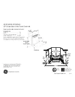
GDF510PSDSS
Brand: GE Pages: 2
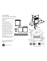
GLD7400R
Brand: GE Pages: 2

GDT550HGD
Brand: GE Pages: 73
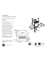
GLD2800T
Brand: GE Pages: 2

GDF510PSDSS
Brand: GE Pages: 48
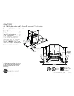
CDWT980RSS - Cafe 24" Tall Tub Dishwasher
Brand: GE Pages: 2
CDWT980RSS - Cafe 24" Tall Tub Dishwasher
Brand: GE Pages: 32

CDT725SSFSS
Brand: GE Pages: 64

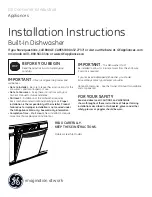
Built-In Dishwashers
Brand: GE Pages: 48
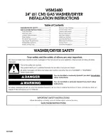
Spacemaker WSM2480
Brand: GE Pages: 12
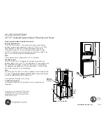
Spacemaker GTUP270EMWW
Brand: GE Pages: 3
Profile WPDH8800
Brand: GE Pages: 80
Appliances GFWN1100
Brand: GE Pages: 54

GLDA696FSS
Brand: GE Pages: 1

GCRH410
Brand: GE Pages: 11

S4930N1
Brand: NEFF Pages: 25

GI53315X
Brand: Gorenje Pages: 30

NTW3811
Brand: Conservator Pages: 48


