background image

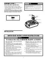
ASSEMBLY STEP 1

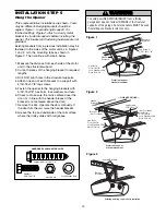
Attach the Rail to the Motor Unit

To avoid installation difficulties, do not run the
garage door opener until instructed to do so.

• Remove the two washered bolts mounted in top of

motor unit.

• Align rail and styrofoam over sprocket. Cut tape

from rail, belt and styrofoam.

• REMOVE STYROFOAM.

• Insert both washered bolts through the rail into the

motor unit. Tighten bolts securely.

Use only these bolts! Use of any other bolts
will cause serious damage to door opener.

• Position belt over the motor unit sprocket.

6

Motor Unit 
Sprocket

Foam Packaging

Washered Bolts
5/16"-18x1/2"

ASSEMBLY STEP 2

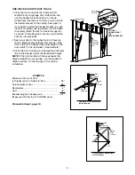
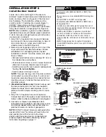
Set the Belt Tension

• By hand, thread the spring trolley nut on the

threaded shaft until it is finger tight against the
trolley (Figure 1). Do not use any tools. 

• Insert a screwdriver tip into one of the nut ring slots

and brace it firmly against the trolley (Figure 2).

• Place a 7/16" open end wrench on the square

end. Rotate about 1/4 turn until the spring releases
and snaps the nut ring against the trolley (Figure 3).

This extends the spring for optimum belt tension.

Trolley
Threaded
Shaft

Spring/Trolley Nut

Nut
Ring

Trolley
Threaded 
Shaft

Nut Ring
Slots

Square 
End

Figure 1

Figure 2

Nut Ring

Trolley

Nut Ring

Trolley

1" (2.5 cm)

1-1/4" (3.18 cm)

BEFORE

AFTER RELEASE

Figure 3

To avoid SERIOUS damage to garage door opener, 
use ONLY those bolts/fasteners mounted in the top of
the opener.

WARNING

CAUTION

WARNING

WARNING

Summary of Contents for security+ 3500D

Page 1: ...ector System is connected and properly aligned Periodic checks of the opener are required to ensure safe operation The model number label is located on the front of your opener GARAGE DOOR OPENER Mode...

Page 2: ...gramming 31 32 To add or reprogram a hand held remote control 31 To erase all codes 31 3 Button Remotes 31 To add reprogram or change a Keyless Entry PIN 32 Repair Parts 33 34 Rail assembly parts 33 I...

Page 3: ...To prevent possible SERIOUS INJURY OR DEATH ALWAYS call a trained door systems technician if garage door binds sticks or is out of balance An unbalanced garage door may not reverse when required NEVE...

Page 4: ...anning Identify the type and height of your garage door Survey your garage area to see if any of the conditions below apply to your installation Additional materials may be required You may find it he...

Page 5: ...l Panel Your garage door opener is packaged in two cartons which contain the motor unit and the parts illustrated below Note that accessories will depend on the model purchased If anything is missing...

Page 6: ...2 Set the Belt Tension By hand thread the spring trolley nut on the threaded shaft until it is finger tight against the trolley Figure 1 Do not use any tools Insert a screwdriver tip into one of the...

Page 7: ...anglement 5 Install garage door opener 7 feet or more above floor 6 Mount emergency release handle 6 feet above floor 7 NEVER connect garage door opener to power source until instructed to do so 8 NEV...

Page 8: ...g horizontal line on the header wall 2 5 cm above the high point This height will provide travel clearance for the top edge of the door Proceed to Step 2 page 10 To prevent possible SERIOUS INJURY or...

Page 9: ...to the remainder See Example 3 Close the door and draw an intersecting horizontal line on the header wall at the determined height NOTE If the total number of inches exceeds the height available in y...

Page 10: ...UNT ONLY Wall Mounting Holes Optional Wall Mounting Holes The nail hole is for positioning only You must use lag screws to mount the header bracket UP CEILING MOUNT ONLY Door Spring Header Bracket 2x4...

Page 11: ...IZE INSTALLATION STEP 3 Attach the Rail to the Header Bracket Position the opener on the garage floor below the header bracket Use packing material as a protective base NOTE If the door spring is in t...

Page 12: ...setting an ideal door to rail distance Remove foam packaging Raise the opener onto a stepladder You will need help at this point if the ladder is not tall enough Open the door all the way and place a...

Page 13: ...ke sure the rail is centered over the door or in line with the header bracket if the bracket is not centered above the door 7 Remove the 2x4 Operate the door manually If the door hits the rail raise t...

Page 14: ...lf tapping screws drywall installation or 6 32x1 machine screws into gang box as follows Drill and install bottom screw allowing 1 8 3 mm to protrude above wall surface Position bottom of door control...

Page 15: ...r end of the rope through the hole in the release arm of the outer trolley Adjust rope length so the handle is 6 feet above the floor Secure with an overhand knot NOTE If it is necessary to cut the ro...

Page 16: ...Connect the black line wire to the screw on the brass terminal the white neutral wire to the screw on the silver terminal and the ground wire to the green ground screw The opener must be grounded Rein...

Page 17: ...he door no more than 6 above the floor Either can be installed on the left or right of the door as long as the sun never shines directly into the receiving eye lens The mounting brackets are designed...

Page 18: ...the lip hugging the back edge of the track as shown in Figure 1 If your door track will not support the bracket securely wall installation is recommended Wall installation Figure 2 and 3 Place the bra...

Page 19: ...sending eye amber indicator light will glow regardless of alignment or obstruction If the green indicator light in the receiving eye is off dim or flickering and the invisible light beam path is not...

Page 20: ...Drill 3 16 fastening holes Secure the door bracket using the two 1 4 14x5 8 self threading screws Figure 2A Alternately use two 5 16 bolts lock washers and nuts not provided Figure 2B Metal insulated...

Page 21: ...he door if required for your installation Refer to the dotted line optional placement drawing Header Wall Vertical Centerline of Garage Door Finished Ceiling Optional Placement of Door Bracket Header...

Page 22: ...3 Hole alignment alternative If holes in curved arm are above holes in straight arm disconnect straight arm Cut about 6 from the solid end Reconnect to trolley with cut end down as shown Bring arm sec...

Page 23: ...e 5 16 x1 1 4 clevis pin and ring fastener NOTE Adjusting the limits on the following page The trolley will automatically connect If not review the trolley lockout feature on page 28 When setting the...

Page 24: ...ts To program the travel limits 1 Press and hold the black button until the yellow indicator light starts flashing slowly then release 2 Push and hold the black button until the door reaches the desir...

Page 25: ...and DOWN in order for the force to be set properly If the unit cannot open and close your door fully inspect your door to insure that it is balanced properly and is not sticking or binding See page 3...

Page 26: ...opener ADJUSTMENT STEP 4 Test The Protector System Press the remote control push button to open the door Place the opener carton in the path of the door Press the remote control push button to close t...

Page 27: ...Bulb size is 100 watts maximum Security light feature Lights will also turn on when someone walks through the open garage door With a Motion Detecting Control Panel this feature may be turned off as...

Page 28: ...lashing The Lock feature will also turn off whenever the Learn button on the motor unit panel is activated Additional features when used with the 3 Button hand held remote A To control the opener ligh...

Page 29: ...e living quarters the Vibration Isolator Kit 89LM can be installed This kit was designed to minimize vibration to the house and is easy to install HAVING A PROBLEM 1 The opener doesn t operate from ei...

Page 30: ...The door reverses for no apparent reason and opener lights blink for 5 seconds after reversing Check the safety reversing sensor Remove any obstruction or align the receiving eye See Installation Step...

Page 31: ...ntrol Panel 3 Continue holding both buttons while you press the push bar on the Motion Detecting Control Panel all three buttons are held 4 Release buttons when the motor unit lights blink It has lear...

Page 32: ...buttons for the present PIN then press and hold the button The opener light will blink twice Release the button 2 Press the new 4 digit PIN you have chosen then press Enter The motor unit lights will...

Page 33: ...trol panel 2 373LM 3 Button remote control 3 10A20 3V2032 Lithium battery 4 29B137 Remote control visor clip 5 41A2828 Emergency release rope handle assembly 6 41B4494 1 2 Conductor bell wire white wh...

Page 34: ...41C5839 High voltage wire harness 41B5806 1 DC motor wire harness 41C5418 Light socket wire harness 5 41D605 1 Motor 80kg 100kg KEY PART NO NO DESCRIPTION 6 41DB001 Receiver logic board assembly with...

Page 35: ...include Lock Feature to lock out outside radio signals while you are away from home and turn opener lights on or off from the control panel Garage Door Monitor Security for the largest door of your ho...

Page 36: ...for warranty repair Products returned to Seller for warranty repair which upon receipt by Seller are confirmed to be defective and covered by this limited warranty will be repaired or replaced at Sell...

Reviews: