background image

3

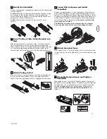
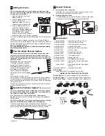
Install the Chain/Belt

Remove chain/belt from carton and lay chain out on floor (do not allow
chain/belt to twist). 

A. Chain:

Push pins of master link bar (3) through chain link (4) and

hole in trolley (5).(see picture) Push cap (2) over pins and onto
notches. Slide clip-on spring (1) over cap and onto pin notches until
both pins are securely locked in place.

B. Belt

: Hook the trolley connector (6) into the slot (7) on the 

trolley (8).

6

Insert Trolley & Idler Pulley Bracket into
Rail

Slide idler pulley bracket (1) and inner trolley (2) into back (opener)
end of rail assembly (3), be sure to insert idler pulley bracket as
shown. Arrow on trolley (7) must face toward front (header) end of rail
(4). Push idler pulley bracket toward front (header) end of rail (4).
Insert carriage bolt (5) into bolt cut out in the idler pulley bracket (6).

7

Attach Trolley to Rail

Slide outer trolley (1) into back (opener) end of the rail assembly (2),
be sure end with trolley release arm (3) is heading in direction of
opener. Slide outer trolley down rail until it engages with inner trolley.

8

A

7

B

6

8

- 1/2”

1

5

4

A-1”

5

4

2

1

2

3

3

1

2

3

4

5

7

5

4

6

1

3

2

1

3

2

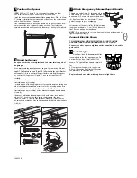
Fasten Rail to Opener and Install
Chain/Belt

Remove four washered bolts (1) from top of opener. Place rail (2) on
opener, flush with stop (3) on top of opener. Wrap chain/belt (4) over
sprocket (5). Push idler pulley bracket assembly toward front of the rail
to eliminate excess slack in chain/belt. Align bolt holes on brackets (6)
with bolt holes on opener. Secure brackets to opener with previously
removed  bolts. Tighten bolts securely. 

The opener sprocket teeth

must engage the chain/belt.

CAUTION: Use only those bolts mounted in the top of opener.
Use of any other bolts will cause serious damage to opener.

9

3

1

3

1

4

6

7

4

7

6

2

2

5

5

3

4

6

7

Attach Sprocket Cover

Place sprocket cover (1) on top of the opener (2), secure with screws
(3). Insert bolt (4) into trolley stop hole (5), secure with washer (6) and
nut (7).

10

6

3

2

5

4

3

2

6

1

8

7

1

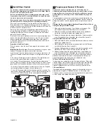
Assemble Header Sleeve and Tighten
Chain/Belt

Slide header sleeve (1) onto rail (5). Slide flat washer (3), spring (2)
and washer (3) onto carriage bolt (4). Thread nut (6) onto carriage bolt
until finger tight. Use an open end wrench (7) to tighten nut until the
chain/belt is approximately 2mm above the base of the rail at its
midpoint. 

DO NOT OVER TIGHTEN THE CHAIN OR BELT.

See

image (8). 

11

3

5

1

6

2

3

4

5

1

6

2

4

5

3

114A3356

Summary of Contents for LM60K-MB

Page 1: ...Instructions Garage Door Operator Model LM60K MB LM60R MB 114A3356...

Page 2: ...doors must be repaired Garage doors door springs cables pulleys brackets and their hardware are under extreme tension and can cause serious personal injury Do not attempt to loose move or adjust them...

Page 3: ...crew 19 Stop Bolt 20 Carriage Bolt 21 Spring 22 Flat Washer Hardware Provided 3 4 Assemble the Rail Grease inside edges of rail sections using grease 1 Place rail pieces 2 on flat surface for assembly...

Page 4: ...3 3 1 2 3 4 5 7 5 4 6 1 3 2 1 3 2 Fasten Rail to Opener and Install Chain Belt Remove four washered bolts 1 from top of opener Place rail 2 on opener flush with stop 3 on top of opener Wrap chain bel...

Page 5: ...nto the ceiling Center the header bracket 1 on the vertical mark no more than 150 mm 6 from the wall Make sure the arrow is pointing toward the opener Mark all of the header bracket holes 5 Drill 4 5...

Page 6: ...a sturdy metal bracket not supplied 4 to a structural support before installing the opener For concrete ceiling mount Figure C use concrete anchors 5 provided On each side of opener measure the dista...

Page 7: ...6 4 5 7 3 Fasten Door Bracket If you have a canopy garage door a door arm conversion kit is required Follow the installation instructions included with the replacement door arm Exercise care in removi...

Page 8: ...off whenever the LEARN button on the control panel is activated 4 2 3 1 WHT 2 RED 1 5 6 6mm 1 2 4 WHT RED 1 4 LOCK LIGHT 3 3 2 3 Program your Opener Remote Activate the opener only when door is in fu...

Page 9: ...2 minutes Press again to turn it off sooner Lock feature Designed to prevent operation of the door from hand held remote controls However the door will open and close from the Door Control the Outsid...

Page 10: ...he door will not move up more than 500mm 27 2 4 2 2x 3 1 Install the Protector System See accessories The force as measured on the closing edge of the door should not exceed 400 N 40kg If the closing...

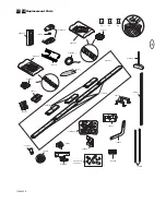
Page 11: ...1A2828 12B374 178B34 178B35 178B69 41B4616 4A1008 1 2 109A46 1 83A11 41A5643 3 12VDC Pb Cd Hg 12B380 12C778 41A5800 12C855 183D177 183D178 41A5887 31D536 31D533 41A5843 41A5801 210C42 12C777 144C77 14...

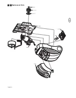
Page 12: ...11 Replacement Parts 31 32 41A589 1 41A5797 41A5734C 111A79 41D577 108C83 41A5908 158A49 114A3356...

Page 13: ...pener strains Door may be unbalanced or springs are broken Close door and use manual release rope and handle to disconnect trolley Open and close door manually A properly balanced door will stay in an...

Page 14: ...o pull the door opener or closed When the Opener is Activated by Remote Control or Lighted Door Control Button 1 If open the door will close If closed the door will open 2 If closing the door will sto...

Page 15: ...repaired or replaced unit or replacement batteries A product under warranty which is determined to be defective in materials and or workmanship will be repaired or replaced at Liftmaster s option at n...

Page 16: ...114A3356 2006 All rights reserved...

Reviews: