background image

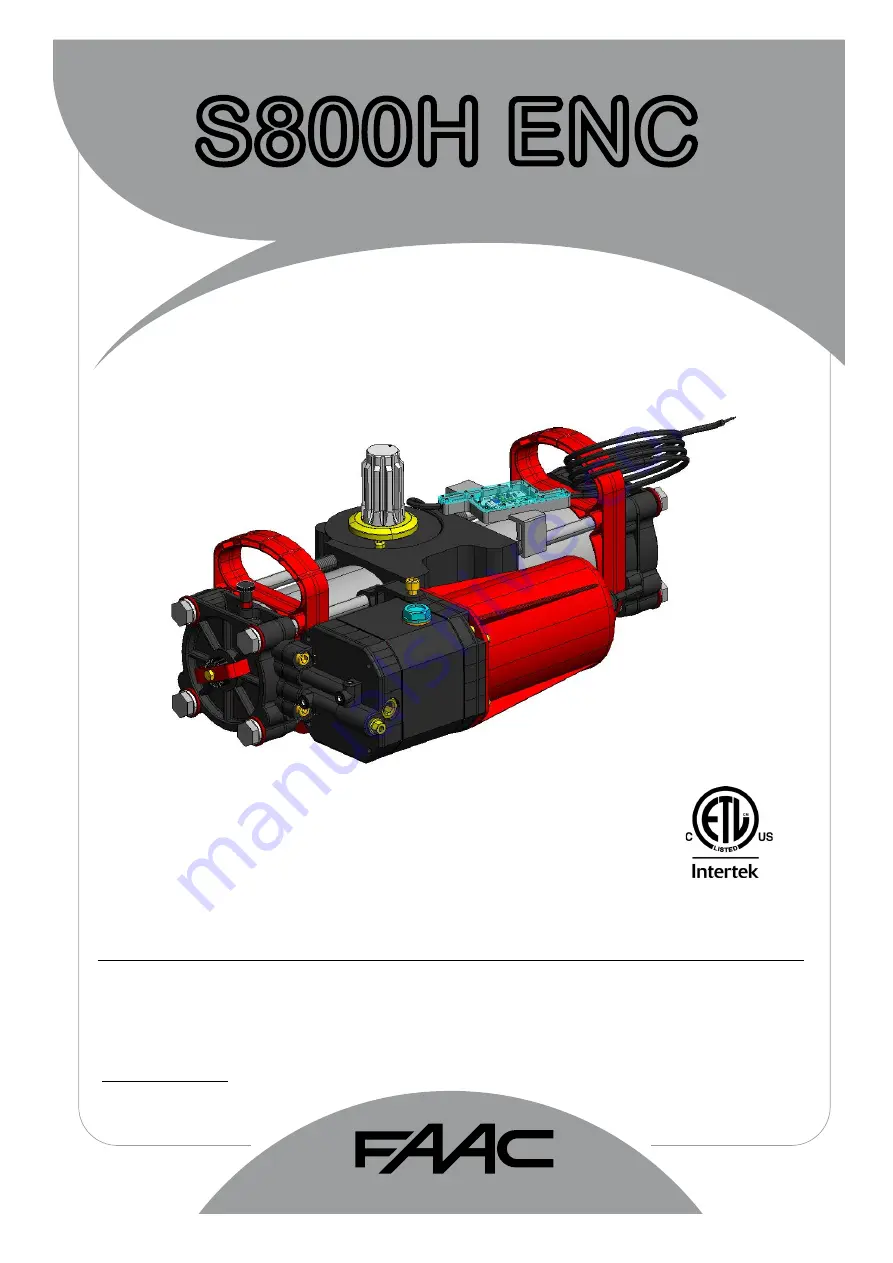
S800H ENC

24V Underground Hydraulic Swing Gate Operator

FAAC International Inc.

West Coast Operations

357 South Acacia Avenue

Fullerton, CA 92831

UL325 - UL991

FAAC International Inc.
Headquarter & East Coast Operations
3160 Murrell Road
Rockledge, FL 32955
Tel. 800 221 8278
www.faacusa.com

Summary of Contents for S450H

Page 1: ...g Gate Operator FAAC International Inc West Coast Operations 357 South Acacia Avenue Fullerton CA 92831 UL325 UL991 FAAC International Inc Headquarter East Coast Operations 3160 Murrell Road Rockledge FL 32955 Tel 800 221 8278 www faacusa com ...

Page 2: ...6 1 1 Technical Specifications 6 1 2 Electrical Layout 6 2 INSTALLATION OF THE SUPPORT BOX 7 3 INSTALLATION THE OPERATOR 8 3 1 Internal Mechanical Positive Stops 10 3 2 Adjustment Of The Travel Limit Stops 10 3 3 Final Steps 10 4 MANUAL OPERATIONS 11 4 1 Built In Hydraulic Release 11 4 2 External In Hydraulic Release 11 5 MAINTENANCE 12 5 1 Bleeding Operations 12 6 ENCODER CONNECTION 14 7 S800H PA...

Page 3: ...e located within line of sight of the gate Activation of the reset control shall not cause the operator to start 7 All warning signs and placards must be installed and easily seen within visible proximity of the gate A minimum of one warning sign shall be installed on each side of the gate 8 For gate operators that utilize a non contact sensor photo beam or the like See instructions on the placeme...

Page 4: ...system component malfunctions disconnect the main power before attempting to repair it Do not impede the movement of the gate you may injure yourself or damage the gate system as a result This equipment may reach high thermal temperatures during normal operation therefore use caution when touching the external housing of the gate operator Use the manual release mechanism according to the procedure...

Page 5: ... loading docks or other locations not intended to service the general public RESTRICTED ACCESS VEHICULAR GATE OPERATOR CLASS IV A vehicular gate operator system intended for use in guarded industrial locations or buildings such as airport security areas or other restricted access locations that do not service the general public and in which unauthorized access is prevented via supervision by secur...

Page 6: ...erating The model without a hydrau lic lock device SBW requires an electrical locks to ensure that the leaf is mechanically locked The S800H ENC operator is designed and built to automate swing leaf gates Do not use for any other purpose TECHNICAL SPECIFICATIONS CBAC OPERATOR SBW OPERATOR Power supply 24 Vdc Absorbed power 60 W Protection class IP 67 Type of oil FAAC HP OIL Operating ambient tempe...

Page 7: ... 3 16 2 1 4 2 3 4 5 1 10 5 8 18 7 8 9 13 16 2 1 27 32 Drain 6 7 Dimensions in inches 2 INSTALLATION OF THE SUPPORT BOX TO ENSURE A CORRECT INSTALLATION THE LEAF ROTATION AXIS MUST BE PERFECTLY ALIGNED WITH THE OPERATOR 7 ...

Page 8: ...rect alignement of the pinion with the splined collar during installation 5 Turn the pinion of the operator using the supplied plastic wrench in the closing direction until it reaches the internal stop of the piston and remove the wrench Fig 5 3 INSTALLATION OF THE OPERATOR 2a Turn the pinion with the supplied wrench counterclockwise by about 20 as shown in Fig 3a Fig 3a 6 Without moving the pinio...

Page 9: ...s in paragraph 3 2 14 Open the gate and check if the opening travel limit stop is correctly positioned if necessary adjust the travel limit stop referring to the instructions in paragraph 3 2 15 Hydraulically re lock the operator 7 Turn the operator pinion with the supplied wrench until it points to the open position 90 from close and then remove the wrench see Fig 7 Fig 8 8 Grease the pinion and ...

Page 10: ...until it encounters resistance Do not force 5 Fasten the supplied U bracket Fig 13 on the travel limit stop nut 6 Manually put the leaf in the open position 7 Unscrew the cap of the screw Fig 12 ref A of the opening travel limit stop Fig 12 ref 2 8 UNSCREW the travel limit stop screw Fig 12 ref 2 until the leaf encounters resistance Do not force 9 Fasten the supplied U bracket Fig 13 on the travel...

Page 11: ...s and banjo bolts and then bleed the system as shown in section 4 2 2 Inspect for leaks if you find any repeat the above steps 7 Fasten the external release body to the load bearing box system using the two supplied M8 screws Fig 19 ref 1 20 Nm Fig 20 The installation of the hydraulic release could have let air in the circuit causing irregular operation like an incorrect movement of the leaf and e...

Page 12: ... Tighten the bleed screw before the operator ends the closing cycle 9 Repeat the operations if necessary 10 Restore the oil level until it is just under the cap using the oil supplied Fig 22 ref 1 The presence of air in the hydraulic circuit causes the automa ted system to operate incorrectly i e a faulty movement of the leaf encoder faults and too much noise while operating Please refer to the pr...

Page 13: ...g wiring error both encoders with the same polarity Power OFF and no communication eg no power or no connection DL 2 Encoder assigned to Leaf 1 Encoder assigned to Leaf 2 DL 3 Encoder generating pulses during leaf movement Leaf not moving To verify the proper assignement of LEAF 1 ENCODER 1 MOTOR 1 and LEAF 2 ENCODER 2 MOTOR 2 use the LEDs visible through the encoder control board shell as shown i...

Page 14: ...nk 09 63000306 Gasket 10 63000376 Motor and Flange 11 7090100025 O Ring 72 69x2 62 mm 13 63001665 Motor Wire Harness Part Part Number Description 14 701103 Screw M4x12 mm SS 15 7090190015 O Ring 14x1 78 mm 16 63002635 Motor Cover 17 63000376 Motor and Flange 18 701072 Screw 5x14 mm 19 70195 Screw M4x75 mm SS 20 701245 Screw M6x8 mm 21 63000256 Splined Joint 22 7110015 Oil Cap 23 63000246 0 5 Lt mi...

Page 15: ... Box Steel 12 714019 Qt 1 FAAC Oil 1 qt 12 7140251 Qt 1 FAAC Arctic Oil 1 qt 13 2182 1 Seal Kit 14 63000106 Piston Part Part Number Description 15 63000056 Pinion 16 63000046 Body 17 63000086 Rack 100 Degree 18 63000016 Bleeding Valve 19 63000146 Flange Right 20 63000036 Positive Stop 21 63000156 Retract Tube 100 Degree 22 63000066 Lower Bushing Group 23 63000206 IGUS Bushing 24 63000196 O Ring 50...

Page 16: ... supply Programming With trimmers dipswitches and pushbutton RADIO Connector for the radio receiver BATTERY Connector for the backup battery J24 Jumper to disable battery charging With the jumper present the battery charger is enabled POWER SUPPLY DC Power supply input TR1 to TR6 Programming Trimmers 24 LED DC power indicator SW1 SETUP Pushbutton for automatic setup DS1 DS2 Programming dipswitches...

Page 17: ... negative for warning lamp DS1 SW12 OFF 24 Vdc negative for safety TX photocell monitored DS1 SW12 ON IMPORTANT for UL325 compliance the negative TX photocell option must be used 10 FCA 1 Open limit switch Motor 1 11 GND 24 Vdc negative 12 FCC 1 Close limit switch Motor 1 13 FCA 2 Open limit switch Motor 2 14 GND 24 Vdc negative 15 FCC2 Close limit switch Motor 2 LAMP LAMP Audio Alarm output DS1 S...

Page 18: ... for protecting the area between the opening leaves and fixed obstacles walls etc against the risk of entrapment Closing Safety Devices Are active only during the gate closing movement and are suitable for protecting the closing area against the risk of entrapment Monitored Devices Additionaly the UL325 standard requires that every external entrapment protection device must be monitored for presen...

Page 19: ... the gate opening and closing move ments and are suitable to protect the opening and closing areas against the risk of impact Typically these photocells work in combination with other monitored photocell pro tecting closing or opening entrapment zones In that case they can t be monitored so they can only protect against potential impact on vehicles CLOSE SAFETY MONITORED CL OP FSW OPEN CLOSE SAFET...

Page 20: ... one closes During the mo vement a command stops the gate AP Automatic step by step OFF ON ON 0 4 min One command opens waits for the pause time and then closes automatically A command during the pause time holds the gate open SP Security step by step ON OFF OFF 0 4 min One command opens waits for the pause time and then closes automatically If the closing safety is activated during pause time the...

Page 21: ...AUSE TIME ADJUSTMENT 0 4 min Turn clockwise to increase the pause time TR6 CLOSING DELAY OF LEAF 1 OVER LEAF 2 ADJUSTMENT 0 15 sec Turn clockwise to increase the delay TR1 FORCE ADJUSTMENT MOTOR 1 Turn clockwise to increase the opening and closing force 1 min 2 min 3 min 4 min 0 sec 30 sec TR 2 FORCE ADJUSTEMENT MOTOR 2 Turn clockwise to increase the opening and closing force 4 2 ADJUSTING TRIMMER...

Page 22: ...ty With SW8 OFF the gate movement will be reversed as soon as the safety is active with SW8 ON the gate will stop when the safety is active and it will reverse only when the safety is deactivated again immediate reverse default OFF reverse when cleared ON PREFLASHING SW 9 This function activates the flashing lamp for 5s before the movement of the gate inactive default OFF active for 5 sec ON EXTRA...

Page 23: ...0H S800H OFF OFF OFF S418 OFF OFF ON 415 390 770 ON OFF OFF DS 2 LOCK OUTPUT MODE OUTPUT MODE SW 4 Active only for 3 sec after an open impulse from gate closed OFF Active always except 3 sec before an opening ON SETTING DL 1 DL 2 DL 3 DL 4 DL 5 J24 IMPORTANT 4 4 DIP SWITCH DS2 SETTINGS FOR OPERATOR TYPE AND LOCK MODE 5 LED DIAGNOSTICS A9 ...

Page 24: ... B active OPEN B not active LED DL 16 STOP INPUT N C STOP non active STOP active or wiring error LED DL 17 FSW CL INPUT N C Closing safety devices clear Closing safety devices triggered or wiring error LED DL 18 FSW OP INPUT N C Opening safety devices clear Opening safety devices triggered or wiring error 9 LED DL 19 FCA1 OPEN LIMIT SWITCH MOT1 N C Limit switch OFF or not used Limit Switch activat...

Page 25: ...n motor 1 or motor 2 error Verify the encoder wiring and LED status If they are correct replace the encoder Verify motor and encoder wire gauge are correct Verify operator is not on manual and hydraulic units don t need to be bled 6 FAIL SAFE FAILED Verify the photocells wiring and alignement 7 BOARD THERMAL PROTECTION ACTIVE Turn off the board and wait until the components cool down 8 MAX RUN TIM...

Page 26: ...and sensitivity using the trimmers 15 15 32 6 7 32 17 15 32 The E024U board is supplied on a panel that fits in a 16x14 enclosure 6 3 OBSTACLE DETECTION FUNCTION 7 ENCLOSURE 1 Apply resistance to the gate and adjust the Force to make sure that the operator creates enough thrust to reliably move the leaf 2 Set the desired speed Keep the speed relatively low on big and heavier gates 3 After Force an...

Page 27: ...ollowing guidelines when installing the AC power 1 Check the local wiring codes in all cases and follow all local building codes Wiring and hookup should be performed by a qualified electrician installer only 2 AC power should be supplied from a circuit breaker panel and must have its own dedicated circuit breaker This supply must include a green ground conductor 3 Use copper conductor wires with ...

Page 28: ... file supplied by FAAC Then follow these steps WARNING Only upgrade the firmware with the proper file supplied by FAAC otherwise the board could be damaged The E024U board keeps the operating firmware in a field pro grammable memory it can be easily upgraded through the on board USB port 10 FIRMWARE UPGRADE The E024U board allows the connection of a 24V backup batterytoprovidepowertooperatethegate...

Page 29: ...at release OPEN stops saves CLOSE OPEN recloses leaves immediately 1 recloses leaves immediately no effect OPEN CLOSE disabled no effect no effect CLOSE disabled no effect OPEN CLOSE disabled CLOSING reopens leaves immediately reopens leaves immediately stops operation no effect reverses at opening stops and opens at release OPEN stops saves CLOSE BLOCKED closes leaves closes leaves no effect OPEN...

Page 30: ...CLOSE disabled recharges pause time CLOSE disabled CLOSING reopens leaves immediately reopens leaves immediately stops operation no effect reverses at opening see DS1 SW8 stops and opens at release OPEN stops saves CLOSE BLOCKED closes leaves closes leaves no effect OPEN CLOSE disabled no effect OPEN disabled no effect CLOSE disabled no effect OPEN CLOSE disabled 1 if the cycle began with OPEN B l...

Page 31: ...E disabled no effect OPEN disabled no effect CLOSE disabled no effect OPEN CLOSE disabled LOGIC C CONTINUOS COMMANDS PULSES SYSTEM STATUS OPEN A OPEN B STOP FSW OP FSW CL FSW CL OP CLOSED opens the leaves no effect no effect OPEN disabled no effect OPEN disabled no effect no effect OPEN disabled OPENING no effect closes leaves stops operation reverses at closure no effect stops and at release clos...

Page 32: ...en subject to misuse negligence or accident or has not been operated in accordance with FAAC International Inc s or FAAC S p A s instructions or has been operated under conditions more severe than or otherwise exceeding those set forth in the specifications for such product s Neither FAAC S p A nor FAAC International Inc shall be liable for any loss or damage whatsoever resulting directly or indir...

Reviews: