background image

 3 

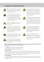
Important safety instructions

To prevent serious injuries resulting from loose parts
getting caught in the machinery, any cables or chains
connected to the door must be removed before you
install the door operator.

The three-button unit, the main disconnecting switch
and all other control equipment must be installed
within view of the door and out of reach of children.
Children should never be allowed to operate buttons
or remote control units. Misuse of the door opener 
can lead to serious injuries.

When installing and connecting the equipment, the
locally applicable building and electrical regulations
must be observed. Electricity cables may only be
connected to a properly earthed network.
Do not install this equipment in damp or wet rooms.

Only one person at a time should ever carry out
works to the door opener.

Live and moving parts of electrical machines can
cause serious or fatal injuries. Assembly, connection
and initial operation as well as servicing and repair

works may only be carried out by qualified specialist

personnel.

When working on the door opener, all local safety
guidelines must be observed. This device must be
installed in accordance with EN12453.

The operator may only be connected and operated in
accordance with the door standard EN: 13241-1 or
with the domestic standard EN 60335-1.

The door opener may only be operated if the person
operating the equipment can see the entire door
area, the door area is free of obstructions, and the
door opener is properly adjusted. No one may walk 
through the doorway when the door is in motion. 
Children should never be allowed to play near the 
door.

Before carrying out repair works or removing covers
from the door opener, install switch locks or discon-
nect the system from the power supply to ensure
that the operator cannot be set in motion unintenti-
onally.

All catches, fasteners and locks must be disabled
to prevent damage being caused to the door or the
door operator. Fix all catches, fasteners and locks in
the „open“ position. If a fastener needs to remain
operational, a release switch must be installed.

The technical data of the geared motor can be found on the identification plate or in 

the accompanying documentation.

The following must be observed

:

- these instructions
- all further engineering documents relating to the door operator
- commissioning instructions and circuit diagrams
- the current national regulations (health and safety)

Warranty, storage

Compliance with the advice and instructions in this leaflet is the basis for trouble-free operation and for the acceptance of any warran

-

ty claims. Please check the contents of the package immediately on delivery for any transport damage. Report any damage immediately
to the transport company and also to the supplier. If you do not intend to install the geared motor immediately, store it in a dry, dust-
free, low-vibration room at a temperature between –10°C and +60°C.

Condition on delivery

Every geared motor is manufactured in accordance with the technical documentation applicable at Chamberlain and is subjected to
a test run. The technical data and design are subject to alterations, in the interest of technical progress. The equipment is shipped in
appropriate packaging.

Summary of Contents for DKK Series

Page 1: ...BEDIENUNGSANLEITUNG Industrietorantriebe DKK WKK DKN WKN DKS WKS ...

Page 2: ...barkeit hin ausgelegt und geprüft worden diese kann jedoch nur gewährleistet werden wenn bei der Installation und Bedienung die nachstehend aufgeführten Sicherheitsvorschriften genau eingehalten werden Dieses Symbol steht vor Hinweisen deren Nichteinhaltung zu schweren Personen bzw Sachschäden führen kann Das Tor muss ausbalanciert sein Bei der Wartung bzw Installation des Toröffners ist geeignete...

Page 3: ...gsgemäß eingestellt ist Niemand darf durch das Tor hindurchgehen solange es in Bewegung ist Kindern darf das Spielen in der Nähe des Tores nicht erlaubt werden Vor der Durchführung von Reparaturen oder dem Entfernen von Abdeckungen am Toröffner ist durch Schaltsperren bzw Abklemmen sicherzustellen dass niemand den Antrieb versehentlich in Gang setzen kann Zur Vermeidung einer Beschädigung des Tore...

Page 4: ...tödliche Verletzungen zu vermeiden ist bei der Aufstel lung folgendes zu beachten Voraussetzung für eine ausreichende Bemessung der Welle hinsichtlich der Dauerfestigkeit ist ein spannungs freier Einbau und eine unverschiebliche Lagerung der Auflager im Getriebe sowie der bei Bedarf vom Anwender zusätzlich beigestellten und erforderlichen Stützlager in jede Richtung Der Maschinenrahmen und die Kra...

Page 5: ...eschädigt und nicht blockiert ist der Antrieb nach längerer Lagerzeit neu vorbereitet wurde die Zuleitung abgeschaltet und gegen wiedereinschalten gesichtert ist VDE alle Anschlüsse ordnungsgemäß ausgeführt wurden die Drehrichtung des Getriebemotors richtig ist alle Motorschutzeinrichtungen aktiv sind keine anderen Gefahrenquellen vorhanden sind Montageanordnung Hinweis zur Installation Elektrisch...

Page 6: ...ild des Antriebs an 3 nennen Sie Art und Ausmaß der Störung 4 nennen Sie wann und unter welchen Begleitumständen die Störung aufgetreten ist 5 der Antrieb keiner Drehzahlschwankung oder anderen Auffälligkeiten unterliegt Elektrischer Anschluss Vor der Installation von Stromkabeln und Steuerungsvorrichtungen müssen unbedingt alle nachste henden Spezifikationen und Warnungen beachtet werden Bei Nich...

Page 7: ...S 4 AS2eco Modell Typ Nm Upm Endschalter Steuerung DKN100240000 DKN100 24 100 24 LSS 6 DKN100240110 DKN100 24 100 24 LSS 4 AS2eco DKN100240440 DKN100 24 100 24 LSS 6 AS210B ZM SKS DKN100241710 DKN100 24 100 24 elektronisch Automatiksteuerung WKN070190000 WKN070 19 70 19 LSS 6 WKK070190130 WKN070 19 70 19 LSS 4 AS2eco WKK070190440 WKN070 19 70 19 LSS 6 AS210B ZM SKS Modell Typ Nm Upm Endschalter St...

Page 8: ...8 Masszeichnungen DKK100 WKK070 ...

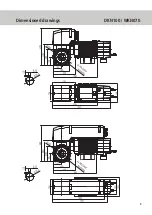
Page 9: ...9 Masszeichnungen DKN100 WKN070 ...

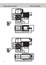
Page 10: ...10 Masszeichnungen DKS100 WKS070 ...

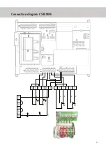
Page 11: ...11 Anschlussplan CS300ME ...

Page 12: ...OPERATING INSTRUCTIONS Industrial door operators DKK WKK DKN WKN DKS WKS ...

Page 13: ...door operator hal been designed and checked for safe operation this can only be guaranteed however if the following safety instructions are observed precisely during installation and operation This symbol indicates important advice where non compliance can result in serious injury and or damage to property The door must be balanced When servicing or installing the door opener suitable protective c...

Page 14: ...No one may walk through the doorway when the door is in motion Children should never be allowed to play near the door Before carrying out repair works or removing covers from the door opener install switch locks or discon nect the system from the power supply to ensure that the operator cannot be set in motion unintenti onally All catches fasteners and locks must be disabled to prevent damage bein...

Page 15: ... To avoid shaft breakages and therefore also serious and fatal injuries the following points must be observed when mounting the equipment A prerequisite for an adequately designed shaft with regard to endurance strength is a tensionless installation and undisplaceable supports for the bearings in the drive unit and for any necessary additional shaft supports in each direction supplied as required ...

Page 16: ...en made ready for use again if it has been in storage for a longer period the input lead is disconnected and secured against being reconnected VDE guidelines all connections have been properly made the rotational direction of the geared motor is correct alle Motorschutzeinrichtungen aktiv sind all motor protection equipment is active Assembly arrangement Installation advice Electrical connection T...

Page 17: ...ibe the type and extent of the malfunction 4 state when and under which conditions the malfunction occurred 5 state wether the operator is affected by fluctations in the rotational speed or other noticeable problems Electrical connection Before you install any electricity cables or control equipment it is imperative that you observe all the following specifications and warnings Non compliance with...

Page 18: ... AS2eco Model Type Nm Rpm limit switch control DKN100240000 DKN100 24 100 24 LSS 6 DKN100240110 DKN100 24 100 24 LSS 4 AS2eco DKN100240440 DKN100 24 100 24 LSS 6 AS210B ZM SKS DKN100241710 DKN100 24 100 24 electronically automatic control WKN070190000 WKN070 19 70 19 LSS 6 WKK070190130 WKN070 19 70 19 LSS 4 AS2eco WKK070190440 WKN070 19 70 19 LSS 6 AS210B ZM SKS Model Type Nm Rpm limit switch cont...

Page 19: ...8 Dimensioned drawings DKK100 WKK070 ...

Page 20: ...9 Dimensioned drawings DKN100 WKN070 ...

Page 21: ...10 Dimensioned drawings DKS100 WKS070 ...

Page 22: ...11 Connection diagram CS300ME ...

Page 23: ...INSTRUCTIONS DE SERVICE Commandes de portes industrielles DKK WKK DKN WKN DKS WKS ...

Page 24: ...ant être garantie que si les consignes de sécurité suivantes ont été scrupuleusement respectées lors de l installation et de l exploitation Ce symbole précède les consignes dont le non respect peut entraîner des dommages corporels ou matériels importants Les Portes doit être équilibrée Lors des travaux de maintenance ou d installation du dispositif d ouverture de la porte il convient de porter des...

Page 25: ...orte lorsque cette zone n est pas encombrée et que le dispositif d ouverture de porte est réglée correctement Personne ne doit traverser la porte tant que celle ci est en mouvement Les enfants ne doivent pas avoir le droit de jouer à proximité de la porte Avant de réaliser des travaux de réparation ou de déposer l habillage du dispositif d ouverture de porte il convient de s assurer par des blocag...

Page 26: ...es graves voire mortelles il convient de respecter les points suivants lors de l installation L une des conditions pour un dimensionnement suffisant de l arbre par rapport à la résistance à l usure réside dans un montage hors tension et un appui fixe sur le support dans l engrenage et des que les appuis nécessaire dans chaque direction qui peuvent être mis à disposition en supplément par l opérate...

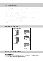
Page 27: ... stockage de longue durée le câble d alimentation est hors tension et sécurisé pour éviter toute remise en marche VDE tous les raccordements ont été réalisés correctement e sens de rotation du moteur réducteur est correct tous les dispositifs de sécurité du moteur sont actives il n y a pas d autres soucres de risques Disposition de montage Consigne concernant l installation Raccordement électrique...

Page 28: ... signalétique de l opérateur 3 indiquez le type et l ètendue du dysfonctionnement 4 indiquez dans quelles conditions et quand le dysfonctionnement est apparu 5 que l opérateur ne présente pas des variations de régime ou d autres éléments suspects Raccordement électrique Avant l installation de câbles électriques ou de dispositifs de commande il convient de respecter impéra tivement toutes les spéc...

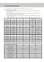
Page 29: ...e Type Nm t m Int de fin de course Commande DKN100240000 DKN100 24 100 24 LSS 6 DKN100240110 DKN100 24 100 24 LSS 4 AS2eco DKN100240440 DKN100 24 100 24 LSS 6 AS210B ZM SKS DKN100241710 DKN100 24 100 24 electronique Commande automatique WKN070190000 WKN070 19 70 19 LSS 6 WKK070190130 WKN070 19 70 19 LSS 4 AS2eco WKK070190440 WKN070 19 70 19 LSS 6 AS210B ZM SKS Modèle Type Nm t m Int de fin de cour...

Page 30: ...8 Croquis coté DKK100 WKK070 ...

Page 31: ...9 Croquis coté DKN100 WKN070 ...

Page 32: ...10 Croquis coté DKS100 DKS070 ...

Page 33: ...11 Schéma de raccordement CS300ME commande ...

Reviews: