


11
Har
dware Setup
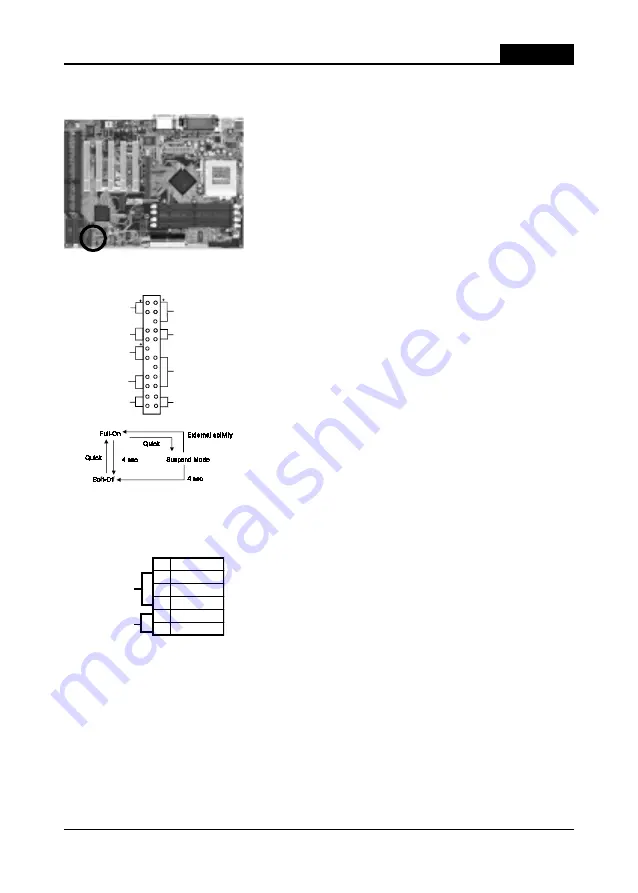
Front Panel Connector Set (CN1) A through G
A. Over-ride Power Button Connector
The power button on the ATX chassis can be used
as a normal power switch as well as a device to
activate Advanced Power Management Suspend
mode. This mode is used for saving electricity
when the computer is not in use for long periods of
time. The Soft-OFF by PWR-BTTN function in
BIOS's Power Management Setup menu must be set
to "Delay 4 Sec." to activate this function. (See
section 3-4)
When the Soft-OFF by PWR-BTTN function is
enabled, pushing the power button rapidly will
switch the system to Suspend mode. Any occurence
of external activities such as pressing a key on the
keyboard or moving the mouse will bring the
system back to Full-On. Pushing the button while
in Full-On mode for more than 4 seconds will
switch the system completely off. See Over-ride
Power Button Operation diagram.
B. Keyboard Lock & Power Indicator LED
Connector
Plugging this connector into the lock on the front
panel of the system case allows the lock to enable
or disable the keyboard. This function provides
limited security against casual intruders. The
power indicator LED shows the system's power
status. It is important to pay attention to the
correct cables and pin orientation (i.e., not to
reverse the order of these two connectors.)
Blinking LED in Suspend Mode
While in Suspend mode, the LED light on the front panel of your computer will
flash. Suspend mode is entered by pressing the Override Power Button, pushing
the Green button on your ATX case, or enabling the Power Management and Suspend
Mode options in BIOS's Power Management menu. (See section 3-4)
P ow e r In d ica to r L E D
S p eake r H e ad e r
G ree n S w itch
Tu rbo L E D
G re e n L E D
R ese t S w itch
O ve r-ride P o w er B u tto n
K eyLo ck
ID E A ctivity LE D
+
Over-ride Power Button
Over-ride Power Button
Over-ride Power Button
Over-ride Power Button
Over-ride Power Button
Operation
Operation
Operation
Operation
Operation
Keyboard Lock
Power Good LED
Pin
Definition
1
+5V DC
2
No Connect
3
Ground
4
Key Lock
5
Ground
Summary of Contents for 6AJM2
Page 3: ...Main Board User s Manual ...
Page 47: ...42 Chapter 4 Memo ...
Page 49: ...44 User s Manual Memo ...


