background image

12

REMOVAL AND REPLACEMENT OF PARTS

Before removing the appliance case,
isolate the gas and electrical supplies.
Isolate the boiler from the system and
drain before removing any component in
the waterways. Ensure that the appli-
ance is cool.

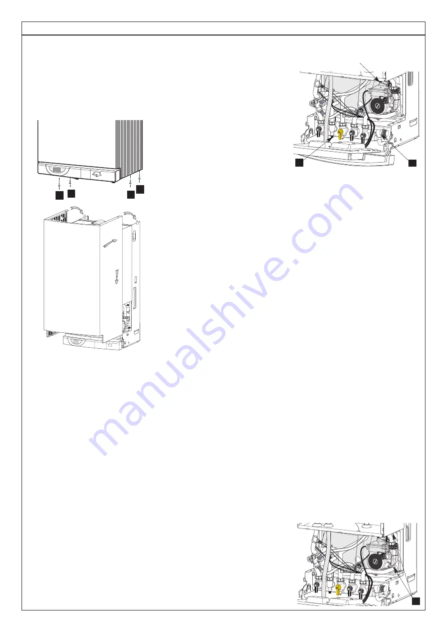
1. Outer Case
Remove the four screws 

in the bottom

of the case and lift free. When replacing,

carefully locate on lugs 

on the top

edge of the chassis.

2. Sealed chamber front panel
Unscrew the four self tapping screws
securing the sealed chamber front panel
and lift over the top corner locating lugs.
Reassemble in reverse order.

3. Combustion Chamber front panel
and air/gas connection
Carry out steps 1 and 2 as above.
Unscrew the three screws securing the
air/gas connection pipe onto the gas
valve assembly. Disconnect the ionisa-
tion and lighting electrodes from their
wiring. Unscrew the six nuts to release
the combustion chamber front panel and
pull the assembly towards you.
Reassemble in reverse order.

4. Ionisation electrode
Carry out steps 1 and 2 as above.
Disconnect the ionisation electrode from
its wiring. Loosen the 2 screws and pull it
out from the combustion chamber front
panel. Replace the ionisation gasket
provided. Reassemble in reverse order.

5. Lighting electrode
Carry out steps 1 and 2.  Disconnect the
lighting electrode from its wiring. Loosen
the 2 screws and pull it out from the
combustion chamber front panel.
Replace the ionisation gasket provided.
Reassemble in reverse order.

6. Burner
Carry out steps 1, 2 and 3.  Remove the
4 Philips screw retaining the burner onto
the combustion chamber. Pull it out with
care to avoid any damage to the ceramic
panel protecting the combustion cham-
ber front panel. Replace the burner gas-
ket. Reassemble in reverse order.

7. Gas vale assembly
Carry out steps 1 and 2  Unscrew the
three screws securing the air/gas con-
nection pipe onto the gas valve assem-
bly. Disconnect the connectors from the
gas solenoids and fan. Loosen the gas
pipe nut.  Unscrew the six nuts to
release the combustion chamber front
panel and pull the assembly towards
you. Replace the gas filter before fitting
the full assembly back into the boiler.

8. Fan assembly
Carry out all the operations mentioned in
step 7.  Unscrew the three screws secur-
ing the air/gas connection pipe onto the
gas valve assembly. Separate the gas
valve assembly and the venturi from the
fan assembly by loosening the two
hexagonal head screws. Reassemble in
reverse order and replace all necessary
gaskets.

9. Gas section
Carry out all operations mentioned in
step 7.  Unscrew the three screws secur-
ing the air/gas connection pipe onto the
gas valve assembly. Separate the gas
valve assembly and the venturi from the
fan assembly by loosening the two
hexagonal head screws. The venturi and
the gas section can be separated by
loosening the 2 screws located at the top
of the gas valve. Replace all necessary
gaskets before reassemble in reverse
order.

10. Venturi in the gas section
Carry out all operations mentioned in
step 7. Unscrew the three screws secur-
ing the air/gas connection pipe onto the
gas valve assembly. Separate the gas
valve assembly and the venturi from the
fan assembly by loosening the two
hexagonal head screws. The venturi and
the gas section can be separated by
loosening the 2 screws located at the top
of the gas valve. Replace all necessary
gaskets before reassembling in reverse
order.

11. Drain down
2 drain points are located on the boiler. 

1 = DHW circuit drain point
2 = Heating circuit drain point

12. Water filters ( DHW and Heating)
The DHW filter ensures a seal between
the connecting bracket and the pipe to
the DHW flow switch. Drain the boiler as
in step 11. Unscrew the pipe nut and
remove the clip on the hydraulic assy.
Pull the pipe toward you and remove the
water filter from its location.
The C.H. filter is located in the right
hydraulic assembly. Remove the return
pipe as described previously and with-
draw the filter. Reassemble in reverse
order.

13. Flow switches
Drain boiler as in step 12. Disconnect
the electrical plug, turn the top cover
anti-clockwise, remove the O-ring and
the brass piston. Reassemble in reverse
order.

14. 3-Way valve
Drain boiler as in step 12. Remove the 3
clips on the 3 way valve. Remove the
clip on the exchanger flow pipe. Pull the
pipe down then pull it out of the 3 way
valve. Disconnect the plug from the
motor. Unscrew the nut on the pipe
between the connecting bracket and the
3 way valve and pull it toward you.
Rotate the 3 way valve body anti-clock-
wise to unclip it from the left hydraulic
assembly.

15. Secondary heat exchanger
Drain both circuits of the boiler as in step
12. Unscrew the 2 fixing screws 

and

remove the DHW exchanger from the
front. Prior to reassembly, check that the
4 gaskets are correctly positioned. The
heat exchanger is so designed that it

A A

A

A

T

T

1

2

1

2

air separator

D

Summary of Contents for Calydra green 24

Page 1: ...as rate C H D H W min 0 64 kg h 0 73 kg h Gas valve restrictor diameter 4 40 mm 4 8 mm 24 kW 30 kW 24 kW 30 kW Heat gross input C H max 9 2 27 8 kW 10 4 31 6 kW Heat gross input D H W max 9 2 27 8 kW 10 4 31 6 kW Heat output C H 50 30 max 9 26 kW 10 30 kW Heat output C H 80 60 max 8 24 kW 9 28 kW Heat output DHW maxi 8 24 kW 9 30 kW C H operating temperature 80 C max 80 C max C H circuit pressures...

Page 2: ...r 0 1 3 4 42 43 44 41 40 45 46 47 1 2 3 4 5 6 8 11 12 13 14 7 15 10 9 16 1 Steel chassis complete with expansion vessel 2 Sealed chamber 3 Burner and heat exchanger assembly 4 Air gas connection 5 24 V modulating fan 6 Gas valve 7 Ignition electrode 8 Ionisation probe 9 Ignitor 10 Combustion products manifold 11 24 V transformer 12 Siphon 13 Electrical box 14 Pump 15 Secondary heat exchanger 16 Pr...

Page 3: ...e tap is opened at the gas meter and the main power is on Green indicator Power ON 36 3 Open the gas tap 42 The boiler is now ready to use Attention If the boiler remains off for a prolonged period of time air may collect in the gas pipes and can hinder the boilers initial attempts to light please refer to section 18 Incorrect Function Switching on the Central Heating Press key 29 the green indica...

Page 4: ...nti freeze function of the room thermostat if fitted To leave the room thermo stat anti freeze system operative please leave the Central Heating mode on The boiler is equipped with an automatic anti freeze system which is permanently on If the Central Heating temperature decreases below 7 C the pump will start If the Central Heating temperature decreases below 4 C the pump and the burner will star...

Page 5: ...nsures accurate temperature regulation When the tap is closed the burner may stay alight until the TSS cylinder is up to temperature Then the burner is extin guished and the pump stops The boiler will now stay in the hot water mode for 3 minutes to maintain temperature to ensure a fast response in the event of a subsequent hot water demand Priority will be given to a demand for hot water or re hea...

Page 6: ...oiler by pressing the reset key 39 Overheat detection If an overheat over 100 C is detected in the primary circuit by the sensor 23 the safety solenoids close and the fan stops The orange LED 37 extinguishes and the pump remains running for 3 minutes The reset will only be possible once the primary temperature has dropped below 76 C CALYDRA GREEN FUNCTIONAL DIAGRAM 17 18 19 20 21 23 24 26 27 28 29...

Page 7: ...urations of the boiler Section Digit 1 Digit 2 and 3 Software version of display PCB 0 10 to 99 Flue type 2 1 FF variable speed Room thermostat is calling for heat 3 0 no 3 1 yes Theoretical position of the 3 way valve 4 0 DHW 4 1 CH DHW flow temperature in Celsius degrees 5 from 00 to 99 TSS temperature in Celsius degrees 6 from 00 to 99 CH flow temperature in Celsius degrees 7 from 00 to 99 Soft...

Page 8: ...rmostat operation 0 0 Burner only 0 1 Burner and pump Pump speed 1 0 High speed 1 1 Low speed Pump post circulation duration 2 0 0 min From 0 to 5 minutes by step of 0 5 min 2 0 5 min 2 1 0 min 2 5 0 min Maximum Central Heating flow temperature 4 50 C 4 80 C C H anti cycling delay 8 0 0 min From 0 to 7 minutes by step of 0 5 min 8 0 5 min 8 2 5 min 8 5 0 min C H maximum output limitation Model 24 ...

Page 9: ...on rate to maximum output set in menu 4 sec tion 9 Central heating temperature is dis played in celsius degrees The 3 dots indicate that the combus tion rate control is ON at maximum output X X Switching off the combustion rate control mode press once press once press once press once press once Effect Display Locking conditions of the combustion rate control mode boiler in stand by mode D H W draw...

Page 10: ...vely Action on burner only or pump and burner change to section 9 Adjustment of C H heat output Press key on D H W side 9 times The display shows 906 which corresponds to the 18 kW which is the factory setting 9 section 9 06 18 kW press setting key on CH side once the 2nd and 3rd digits flash together Then press the or key on the D H W side to change the C H heat output step between 00 and 10 Pres...

Page 11: ...e gas valve assembly and the different transformers in the sealed chamber Check combustion chamber insulation panels for damage Check the lighting and ionisation electrodes condition Clean the burner Never use a metallic brush as this can damage the stainless steel Clean the heat exchanger Never use a metallic brush as this can damage the stainless steel Clean the siphon and pay attention to the a...

Page 12: ...mbly and the venturi from the fan assembly by loosening the two hexagonal head screws Reassemble in reverse order and replace all necessary gaskets 9 Gas section Carry out all operations mentioned in step 7 Unscrew the three screws secur ing the air gas connection pipe onto the gas valve assembly Separate the gas valve assembly and the venturi from the fan assembly by loosening the two hexagonal h...

Page 13: ...reverse order 22 Main control board Carry out step 1 as above and hinge down the electrical box by pressing the retaining tabs P on either side Remove wiring cover C Undo the 4 screws of the electrical rear panel and remove it Unplug all cables from the PCB remove the earth plug from the earth socket Hang out the main PCB Reassemble in reverse order 23 Display PCB Carry out step 1 and hinge down e...

Page 14: ... heating thermistor Check heating thermistor Ok No No No No Yes Yes Yes No No No Ok Ok Ok Ok means a test or a choice means an action means a group of actions error code displayed PLEASE CHECK THE FOLLOWING POINTS CAREFULLY BEFORE GOING THROUGH THE FAULT FINDING CHART Gas pressure Electric mains Minimum water pressure in the heating circuit over 0 8 bar All isolating valves have been opened Boiler...

Page 15: ...between the 2 PCBs Is the combution chamber full of conden sates Yes Check ionisation probe No Ok Drain and clean combustion cham ber siphon and drain pipes Yes Replace the ionisation probe No Stop water draw off Does DHW temper ature rise over 70 C Check DHW ther mistor No Ok Press on DHW key to switch off DHW mode Press on CH key to switch on CH mode and set CH tempera ture to maximum Press the ...

Page 16: ...ED 277884 1003635 630 FUSE 250V 0 315A TEMPORIZED 1307845 640 TRANSFORMER 1308149 805 PRESSURE GAUGE 1303158 938 PRESSURE RELIEF VALVE 1020933 Description Key N Manf Pt N Type G C N Manf date C A L Y D R A G R E E N 2 4 C A L Y D R A G R E E N 3 0 from to 110 407 401 532 505 640 514 510 507 R37 R31 J7 R102 1 8 C68 ST2 FT1A Z11A Z9A R DL1 TH1A Z6A R132 U5 Z5A Z4A TERR E 1 TH1 C83 C78 C80 ST1 R87 Z9...

Reviews: