Operating Manual & Parts List
9681310 & 9681311
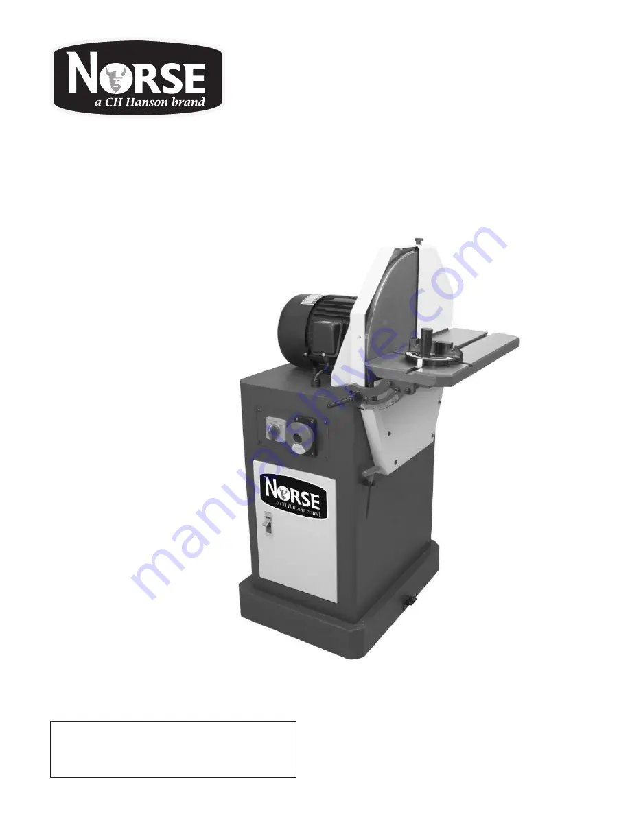
DISC SANDER
with Stand
Read carefully and follow all safety
rules and operating instructions before
first use of this product.
9644211.01-0519
Page 1: ...Operating Manual Parts List 9681310 9681311 DISC SANDER with Stand Read carefully and follow all safety rules and operating instructions before first use of this product 9644211 01 0519...
Page 2: ...Model ___________________ Serial ____________________ Purch Date ________________...
Page 3: ...sing or damaged parts Shipping damage claims must be filed with the carrier All tools should be visually inspected before use in addition to regular periodic maintenance inspections Be sure that the v...
Page 4: ...t force a tool or attachment to do a job for which it was not designed To reduce the risk of electrical shock never use the machine in rain or allow it to become wet Never attach the Disc Sander to a...
Page 5: ...a properly grounded outlet Never operate the machine if it is not properly grounded to help prevent electrical shock Power source The motor on this machine is designed for operation on the voltage and...
Page 6: ...machine uses a 4 diameter dust port Locate the dust port on the left side of the machine Slide a suitable hose over the port and secure it with a hose clamp Dryer vent hosing material is not acceptab...
Page 7: ...m front to back Align the table so the gap between the disc and table is grease Clean the flywheel disc of any left over adhesive dirt or 4 Clean the flywheel disc of any left over adhesive dirt or Cl...
Page 8: ...pointer F to 90 if required 4 miter tool to ensure it is square Carefully tighten the adjustment push knob and recheck the 3 tool face and flywheel disc of the miter tool until the square rests flush...
Page 9: ...cal supply and switch show correct voltage the motor is probably the issue Have a qualified electrician test the motor for function Replace motor as needed On Off switch failure Have a qualified elect...
Page 10: ...SE Operating Manual Parts List 9681310 9681311 10 WIRING DIAGRAM MODEL 9681314 16 DISC SANDER Motor wire outlet Power cord outlet Reversing Switch Pressure Switch WIRING DIAGRAM MODEL 9681310 16 DISC...
Page 11: ...11 NORSE Operating Manual Parts List 9681310 9681311 11 WIRING DIAGRAM MODEL 9681315 20 DISC SANDER WIRING DIAGRAM MODEL 9681311 20 DISC SANDER...
Page 12: ...12 NORSE Operating Manual Parts List 9681310 9681311 14 REPAIR PARTS ILLUSTRATION FOR MODEL 9681314 16 DISC SANDER F REPAIR PARTS ILLUSTRATION MODEL 9681310 16 DISC SANDER...
Page 13: ...Cap Screw 3 8 16 UNC x 7 8 L 3 33 Set Screw 5 16 18 UNC x 3 4 L 2 34 Hub 9642615 01 1 35 16 Disc 9642616 01 1 36 Wheel Washer 9642617 01 1 37 Cap Screw 1 4 20 UNC x 3 4 L 1 38 Abrasive Disc 1 39 Tabl...
Page 14: ...14 NORSE Operating Manual Parts List 9681310 9681311 16 REPAIR PARTS ILLUSTRATION FOR MODELS 9681315 9681316 AND 9681317 20 DISC SANDERS REPAIR PARTS ILLUSTRATION MODEL 9681311 20 DISC SANDER...
Page 15: ...Chute Plate Left 9642656 01 1 28 Dust Chute Plate Right 9642657 01 1 29 Knob 9642613 01 2 30 Flat Washer 5 2 x 16 x 1 4t 2 31 Disc Guard Front 9642659 01 1 32 Cap Screw 3 8 16 UNC x 7 8 L 3 33 Set Scr...
Page 16: ...perating Manual Parts List 9681310 9681311 REPAIR PARTS ILLUSTRATION FOR MITER GAUGE MODELS 9681314 9681315 AND 9681316 DISC SANDERS REPAIR PARTS ILLUSTRATION FOR MITER GAUGE MODELS 9681310 9681311 DI...
Page 17: ...as replacement part 1 Miter Gauge Assembly 9642639 01 1 1 1 Handle N A 1 1 2 Miter Gauge N A 1 1 3 Round Head Screw 3 16 24 UNC x 5 16 L N A 1 Ref No Description Part No Qty Ref No Description Part N...
Page 18: ...NOTES 18 NORSE Operating Manual Parts List 9681310 9681311...
Page 19: ...NOTES 19 NORSE Operating Manual Parts List 9681310 9681311...
Page 20: ...ed solely to the repair or replacement at our option at its factory or authorized repair agent of any part that should prove inoperable Purchaser must lubricate and maintain the product under normal o...