background image

22 


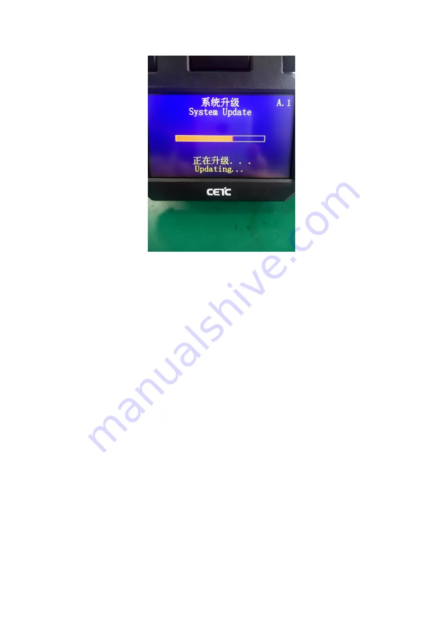
4)  If the upgrade is abnormal, upgrade it again. 


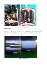
Fig.21 Software upgrade interface 

5.2 Cleaning of V-groove 

In  case  of  the  contaminant  in  V-groove,  the  fiber  may  not  be  properly  clamped,  which  will  cause  the 
larger fusion losses. Therefore, V-groove shall be checked and cleaned regularly during the normal work 
process. Follow these steps to clean V-groove: 

a

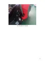
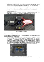
 As shown in Fig.22, open the dust cover; 

b

 Clean the contaminants in V-groove by pushing it with the end of a well-cut fiber along the one 

direction; 

c

 Clean the bottom of V-groove with a fine cotton swab moistened with alcohol, and remove the 

excess alcohol left in the V-groove with a dry cotton swab. 

d

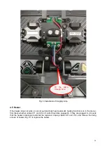
 As shown in Fig.23, clean the fiber presser with a fine cotton swab moistened with alcohol. 


Summary of Contents for 6481 Series

Page 1: ...6481 Series Optical Fiber Fusion Splicer Maintenance Manual China Electronics Technology Instruments Co Ltd...

Page 2: ...4 4 Imaging Lamp 10 4 5 Heater 15 4 6 Power Board 16 4 7 High voltage Board 17 4 8 Control Board 18 4 9 Light Path 20 5 Repair and calibration of Instrument 21 5 1 Software Upgrade 21 5 2 Cleaning of...

Page 3: ...sensor via a special microscope The image characterizes the physical and geometrical positions of the fiber in two directions which are perpendicular to each other The two way fiber images are process...

Page 4: ...ff of touch screen function in the menu 2 Touch screen not calibrated 3 Touch screen cable not plugged 4 Damage of touch screen cable or touch screen 1 Open the touch screen function in the menu 2 Cal...

Page 5: ...Plug in the high voltage discharge plate cable 2 Replace the high voltage discharge plate Discharge to V groove Offset of electrode position Adjust the electrode position Weak or unstable discharge 1...

Page 6: ...quality of fiber cutter Small discharge current or decreasing discharge time Discharge Correction or increase the fusion time Fiber separation Too short propelling distance of fiber Correct the prope...

Page 7: ...otor is stuck manually assist the motor to smoothly pass the jam and enable the instrument to normally start Press the Menu button to enter the menu page select maintenance motor motor adjustment and...

Page 8: ...6 Fig 4 Jam of propel motor...

Page 9: ...s between motor gears Dust accumulates between gears sometimes the foreign objects such as the exterior protection cover is stuck The dust on the fitting part between the propel threaded rod and screw...

Page 10: ...micrometer head gear and if it is too tight or shafts are not parallel adjust the relative positions by loosening the screws of align motor see Fig 8 or if the micrometer head does not rotate smoothl...

Page 11: ...9 Fig 8 Align motor Screws of align motor...

Page 12: ...at the weld point of printed board the imaging lamp and spindle shall be replaced As shown in Fig 10 remove the limiting plate of sketch mounting plate to present the imaging lamp and remove 4 screws...

Page 13: ...le The heat shrink tube on the heat shrink imaging lamp cable is as shown in Fig 14 Insert the pin of imaging lamp cable into the plug that has just been removed the cable is black white and blue in s...

Page 14: ...12 Fig 11 Imaging lamp Screws fixing the imaging lamp Cable at spindle may be damaged Weld point may be broken...

Page 15: ...13 Fig 12 X26 cable X26 cable is black red white and blue in sequence from the inside to the outside Jet out the pin of X26 cable out of plug and do not discard the plug...

Page 16: ...14 Fig 13 Replacement of spindle...

Page 17: ...atic heating function is on in the menu first check whether cables X11 and X12 of control board are plugged in If they are plugged in it means that the heater is damaged and shall be replaced Unplug c...

Page 18: ...ower module is not damaged if not the power module is damaged and proceed to the determination whether the power board or battery is damaged If the power board is damaged remove the screws on the powe...

Page 19: ...mal If the discharge failure still exists the high voltage board is damaged Replace the high voltage board by pulling out the cables X1 and X2 of high voltage board removing two high voltage wires on...

Page 20: ...by extracting the control board if necessary In case the white screen at start pull up the plug of X26 cable imaging lamp on the control board and then restart the instrument If the white screen disa...

Page 21: ...19 Fig 18 Main control panel FPGA load indicator V17 X4 socket...

Page 22: ...th another image In case of dark spots or shadows on the video background of X Y camera there may be the dirt on the X Y camera microscope lens or X Y camera CMOS surface To rectify the fault wipe the...

Page 23: ...he USB flash drive is not in the format of FAT16 FAT32 the system prompts Please insert an upgrade USB flash drive If the FAT16 FAT32 USB flash drive has no upgrade information the system prompts Plea...

Page 24: ...d regularly during the normal work process Follow these steps to clean V groove a As shown in Fig 22 open the dust cover b Clean the contaminants in V groove by pushing it with the end of a well cut f...

Page 25: ...n swab moistened with alcohol or gently rub the tip of electrode with a 3mm wide and 50mm long metallographic sandpaper strip Take care to protect the tip of electrode from damage Regular original ele...

Page 26: ...4 Electrode cap and screw 5 4 Adjustment of Electrode Holder In case of the significant offset of discharge arc or the unstable discharge the electrode holder shall be readjusted according to the foll...

Page 27: ...26 Cleaning of objective lens 5 6 Propelling Distance Correction Place the fiber with well prepared cross section into the fusion splicer select the Propelling Distance Correction item in the motor me...

Page 28: ...as follows a Fusion splicer automatically pushes the fiber to the center of screen and sets the gap b Fusion splicer automatically discharges corrects the arc position and adjust the current c If the...

Reviews: