Ceyear 4957D Quick Start Manual Download Page 21

4957D/E/F Microwave Analyzer Quick Start Guide 

17 


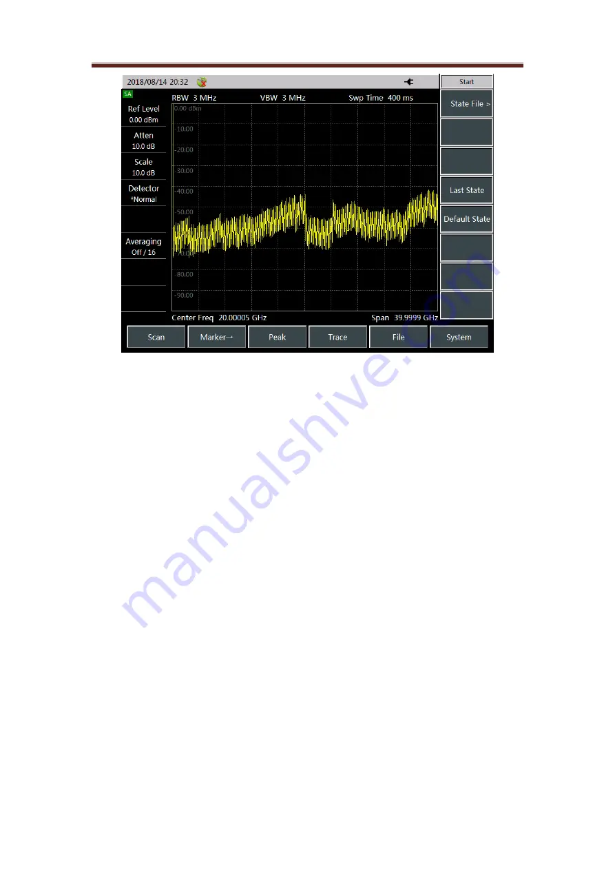
Figure 3.7 Test interface of the SA mode  

2. Setting reference level 

Set reference level in 

the spectrum analysis mode. Press [Amplitude] → [Ref Level], then 

input the value with the numeric keys, and select the corresponding unit from the touch 
screen to complete the input. For Example:  Press 

[Amplitude] → [Refer Level] → [0] → 

[dBm] to set the reference level to 0 dBm. 

3. Setting center frequency 

Press  the  [Freq]  key.  This  operation  activates  the  function  to  set  parameters  like  the 
center  frequency,  allows  the  information  input  zone  to  display  the  current  center 
frequency value, and make the soft menu display the contents corresponding to the [Freq] 
key. Set the center frequency to 300 MHz. Enter [3], [0], and [0] directly with the keys in 
the  data  zone  of  the  front  panel,  and  then  press  the  corresponding  [MHz]  keys.  These 
numeric keys  can  be  used  to  set  exact  values  for the  current  parameters,  and  the  step 
key and the roller can also be used to change the center frequency value. 

4. Setting sweep span 

Press [Freq] 

→ [Span>] Note whether the span data is displayed in the information input 

zone  to  determine  the  currently  activated  parameters.  Reduce  the  span,  to  20MHz,  for 
instance, type [2] and [0] with the data keyboard, select the unit [MHz], or use the [↓] key 
to step down to this value (both numeric keys and step keys can be used to change the 
value of the current parameter). You can also press [Span Zero] or [Span Full] to set the 
min and max sweep spans. Press [Span Pre] to set the value of the previous sweep span. 

5. Activating marker 

4957D/E/F microwave analyzer provides up to eight independent markers for reading out 
the measurement results. Press [Mkr] → [Sel Mkr] → [Mkr 1], [[Mkr 2]…[[Mkr 7], [[Mkr 8] 
to  select  the  currently  displayed  marker.  Each  marker  has  two  working  modes,  normal 
mode  and  delta  mode.  Set  the  marker  to  the  delta  mode.  P

ress [Mkr] → [Delta Mkr] to 

directly  input  the  frequency  delta  value.  You  can  also  move  the  marker  with  the  [↑]  [↓] 
keys or the rotary pulse generator to view the frequency and amplitude delta values. 

Press [Peak] → [Max] and [Min] to let the analyzer automatically search for the max and 
min values of the measurement traces, or perform peak search of the marker, including 

Summary of Contents for 4957D

Page 1: ...4957D E F Microwave Analyzer Quick Start Guide China Electronics Technology Instruments Co Ltd...

Page 2: ......

Page 3: ...duct can meet the indicator requirement in the manual upon delivery The calibration and measurement are completed by measuring bodies with national qualification with relevant data to be provided for...

Page 4: ...A Mode 9 3 2 DTF Measurement in the CAT Mode 15 3 3 Signal Measurement in the SA Mode 16 3 4 Measuring Signal Power in the Power Monitor PM Mode 18 3 5 Measuring the Electrical Length of Cables or Oth...

Page 5: ...the following chapters and sections Get Prepared This chapter introduces the preparation before operation startup panel introduction and battery replacement of 4957D E F After reading this chapter you...

Page 6: ...the instrument not mentioned in the manual Otherwise such consequences as reduced electromagnetic shielding property and internal component damage can occur affecting product reliability In this case...

Page 7: ...e The basic parameters of the enclosed battery are as follows Nominal voltage 10 8 V Nominal capacity 7 800 mAh Working time About 2 5 h Charging time About 6 h Rechargeable batteries should not be ex...

Page 8: ...s on the bottom of the touch screen are represented by XXX with XXX being the name of the key The menu keys on the right are represented by XXX with XXX being the menu name 2 3 Front Panel This sectio...

Page 9: ...ch can be selected as CAT Network Analyzer Spectrum Analyzer Power Monitor USB Power Meter and Voltage Voltmeter etc Cal It is used to select the type of device under calibration piece perform calibra...

Page 10: ...installed power connected b Battery installed and full power connected Flashing yellow a Battery installed and not full power connected Power on Normal on green a Battery not installed power connected...

Page 11: ...arked as 10 MHz In Out with 50 impedance BNC female adapter 4957D E F microwave analyzers can receive externally input 10 MHz sine signals as phase locked reference signals and the input signals shoul...

Page 12: ...ally switched from the speaker to the earphone 2 5 4 Instrument Symbols The instrument symbol yellow label shown in the figure indicates that the max power input from the test spectrum input port and...

Page 13: ...g soft key to select the correct calibration kit model 5 Press OK return to the menu bar of Cal select the frequency response error correction function press M Cal Freq Resp OPEN S11 and the system wi...

Page 14: ...pt Connect Thru cable between P1 and P2 then press corresp menu button to start Then connect N type cable between ports 1 and 2 All adapters or cables used in device measurement should be included i e...

Page 15: ...location where the DUT is to be connected 5 After the display trace is stable press THRU and the analyzer will display Cal std measuring during the measurement of the standard piece and after completi...

Page 16: ...etc 3 Open the calibration menu and press Cal 4 Press Cal Cal Kit to see if the calibration kit is consistent with the kit specified with the current soft key If not press the corresponding soft key t...

Page 17: ...the breaker and connect the load to the test port 10 After the display trace is stable to measure the standard piece press LOAD the analyzer will display calibration standard measurement during the me...

Page 18: ...e and connect the short circuit device to the test port 1 After the display trace is stable to measure the standard piece press P1 SHORT the analyzer will display calibration standard measurement duri...

Page 19: ...layed in the information zone Connect the DUT for measure Figure 3 5 Standard piece connection of full 2 ports error correction In actual calibration there is no sequence for the open circuit device s...

Page 20: ...w to display the submenu of Window and then select different window functions 5 Press Back Unit m ft to set the required distance unit system 6 Press Cable Specification and Load Cable to select the m...

Page 21: ...ency value 4 Setting sweep span Press Freq Span Note whether the span data is displayed in the information input zone to determine the currently activated parameters Reduce the span to 20MHz for insta...

Page 22: ...eed of connection to an external power probe can conveniently test the power of continuous wave signals with a certain bandwidth and the channel bandwidth can be set to a larger value so as to simulat...

Page 23: ...onvenient operation interface as the vector voltmeter The results of single port electrical length measurement are displayed in amplitude and phase formats while the results of all port are only displ...

Page 24: ...port error correction in the VVM mode 5 Selecting measurement mode The VVM mode of the analyzer allows for measurement of parameters of the DUT like amplitude phase VSWR and impedance etc 1 Press Mea...

Page 25: ...USB Power Meter mode and press OK to complete Figure 3 11 Test interface of USB Power Meter mode 2 Connecting power probes 1 As shown in the figure connect the small end of the USB cable to 8723X ser...

Page 26: ...required to set the frequency value of the measured CW Freq signal The USB power probe will store a set of correction factors for each frequency The frequency corresponding to the measured power signa...

Page 27: ...e losses for added attenuators or connecting cables It also allows for setting power offsets for gains of added amplifiers Positive values can compensate losses and negative values can compensate gain...

Page 28: ...F microwave analyzer provides two limit lines upper and lower When the amplitude of a signal in a certain frequency band exceeds the set upper limit or is less than the set lower limit the analyzer w...

Page 29: ...rmat or csv data text format The Print Screen function allows for saving the information displayed on the current screen into the memory of the instrument in an image format The storage medium for sta...

Page 30: ...environment for compliance with the requirements the test port connectors for any damages and the calibration piece for normal performance indicators If everything above is normal the instrument may b...

Page 31: ...g to the following steps 1 Write a paper document describing the instrument failure and put it in the package together with the analyzer 2 Pack it with the original packing materials so as to minimize...

Page 32: ...y 32 dB 40 dB 32 dB 40 dB 28 dB 35 dB Effective source matching 25 dB 37 dB 25 dB 37 dB 18 dB 30 dB Reflected tracking 0 10dB 0 14dB 0 10dB 0 25dB 0 10dB 0 25dB Transmission tracking 0 25dB 0 33dB 0 2...

Page 33: ...nput level 27 dBm Test port type N type female 3 5 mm male 2 4 mm male Power supply Rechargeable li ion battery or power adapter Power consumption 45 W excluding battery charging Working temperature r...

Page 34: ...a test software 4957D S03 Vector voltmeter software 4957D S04 USB power measurement software USB power probe to be equipped separately 4957D S05 Power meter software 4957D S06 Field strength measureme...

Page 35: ...female male calibration cable GORE 0K0CJ0CK024 0 4957D H14 87230 USB CW power probe 4957D H15 87231 USB CW power probe 4957D H16 87232 USB CW power probe 4957D H17 87233 USB CW power probe 4957D H18...

Page 36: ...4957D E F Microwave Analyzer Quick Start Guide 32 4957D H32 Soft backpack 4957D H33 Aluminum alloy carrying case 4957D H34 Waterproof case...

Reviews: