background image


Warrior CB-xW Transmitters 


U114.1.1 

20 

Appendix A: Exposure to Radio Frequency Energy 

Warrior system transmitter and receiver units contain radio transceivers. When active, 
transmitters/receivers send out radio frequency (RF) energy through an internal (or external) 
antenna. The Warrior CB-xW transmitter complies with limits set by the FCC for operating 
distance from human tissue

.


Appendix B: RF Exposure Considerations 

Radio modules may be used in a variety of host applications falling into two general categories: 

1. 

Mobile

 applications: Any operating locations where the transmitting equipment is 

not

 on 

a human body. In mobile applications, the host application is typically fixed to mobile 
equipment, with either an internal or external antenna. 

2. 

Portable

 applications: Any operating locations where the transmitting equipment 

is


located on the hand, arm, or other part of the human body. In portable applications, the 
equipment is either held in the hands of an operator or affixed to either a belt or harness 
on the torso. 

Equipment containing the radio module was evaluated for RF exposure hazards by two 
approaches: 

1.  Maximum Permissible Exposure (MPE) for mobile applications. 

2.  Specific Absorption Rate (SAR) for portable applications. 

Required separation distances are measured from the actual location of the radiating part of the 
antenna. An antenna may be inside the host application, affixed to the host application 
enclosure, or at the end of an optional extension coaxial cable. 

Mobile Applications


Equipment must be located at least 20cm away from areas likely to be occupied by an unaware 
person. 

Transmitter Applications


All operators of transmitter equipment with any type of antenna require proper equipment 
operation training, and such training must include RF exposure safety instructions. They are 
then considered “aware” persons once training is completed. 

If the portable operating position is on the hand or arm, a 5mm separation is required between 
the radiating part of the antenna and nearby human tissue. 

Required Training


All installers and operators of host applications that include an SRF310 FT module 

must

 be 

trained to use proper RF safety precautions as presented in this Appendix. 

Summary of Contents for WARRIOR CB W Series

Page 1: ...2019 Cervis Inc CB xW Transmitters Manual U114 1 1...

Page 2: ...s limites de Sant Canada pour la population g n rale consulter le Code de s curit 6 disponible sur le site Web de Sant Canada https www canada ca en health canada services environmental workplace heal...

Page 3: ...Receiver Unlock 13 2 8 Clearing CB xW Stored Receiver ID Factory Reset 14 2 9 CB xW Advanced Functions 15 2 9 1 Tilt Switch Activation Deactivation 15 2 9 2 Switch Test Mode 16 3 0 Warrior CB xW Cons...

Page 4: ...fore attempting any maintenance This will prevent accidental operation of the controlled machinery Disconnect power from the receiver by either detaching the cable from the receiver or removing the so...

Page 5: ...nowledges each message the transmitter sends via its own acknowledge message Four transmitter diagnostic light emitting diodes LEDs indicate Radio transmission integrity Battery life A B select feedba...

Page 6: ...unction Receiver Communication Association L1 Radio Frequency RF Transmit and Receive indication Flashes when message is sent or received Used for Maintenance Mode MM indication L2 Battery Status indi...

Page 7: ...crolling Tilt Switch Active in Maintenance Mode See Section 2 9 1 Alternating Tilt Switch Inactive in Maintenance Mode See Section 2 9 1 Batteries low replace with fresh batteries soon Receiver also w...

Page 8: ...ose according to local regulations 4 Place two new C cell batteries in the terminal cavity Observe proper polarity with the negative side down and each positive battery terminal up The battery cap int...

Page 9: ...o shutdown The unit will not power up and operate until you replace the depleted batteries Cervis Inc recommends replacing them with two fresh batteries 2 3 Neck Shoulder Harness The 1 wide neck shoul...

Page 10: ...ong quick release hook and loop Nylon rip cord Connect the two parts of the rip cord together and press down to secure the connection 2 3 2 Attaching the Harness to the CB xW Both ends of the high vis...

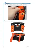
Page 11: ...er the two T shaped harness clips on the front of your CB one is on the left side the other is on the right or the orange bar across the top of it Thread the high visibility orange straps through the...

Page 12: ...Warrior CB xW Transmitters U114 1 1 8 Fold the strap over onto itself and fasten the female snaps to their male counterparts Note You ll know the snaps are secured when you hear a clicking sound...

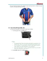
Page 13: ...the ON position Notes The standard Warrior CB xW console box transmitter has a keyswitch on the right hand side Typically this keyswitch enables disables transmitter power It is also possible to use...

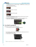
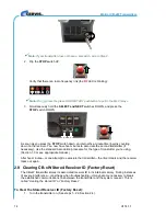
Page 14: ...e process takes approximately five seconds 4 Press the green HORN START pushbutton to energize the receiver s Main Line Contactor MLC relays and begin remote operation of the equipment 2 5 Turn CB xW...

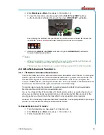
Page 15: ...l from right to left The unit is now in Maintenance Mode Release the switches to perform further operations To Exit Maintenance Mode 1 Press the STOP switch DOWN This also shuts the transmitter down P...

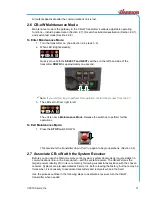
Page 16: ...pting to locate any available receivers to Link to The transmitter builds a list of all possible receiver identities IDs that are in range usually only one 5 When the A and RF LEDs light steadily The...

Page 17: ...will work in a first come first serve fashion where only one transmitter can ever be linked to a receiver unit at a time 2 7 1 Virtual Receiver Unlock When the receiver s Association functionality is...

Page 18: ...itter if necessary Use the standard Association procedure for the type of transmitter you re using Section 1 0 or see appropriate manual After five minutes or one attempt to associate the transmitter...

Page 19: ...up to 60 from level If the transmitter is tilted at 60 or greater for four seconds the accelerometer triggers an internal tilt switch in the transmitter This in turn energizes the receiver s HORN REL...

Page 20: ...he two patterns 6 Once you ve selected your desired mode return the transmitter to its normal operating position 7 Press the green HORN START pushbutton again to set the desired mode 2 9 2 Switch Test...

Page 21: ...nance Mode See steps 1 3 in Section 2 6 3 While in maintenance mode hold the SELECT switch UP for five seconds 4 After five seconds LED B starts blinking Indicating that the transmitter is in Switch T...

Page 22: ...cating that there is a positive connection to one of the analog inputs To Exit Switch Test Mode Either 1 Press the STOP button 2 Turn the keyswitch to the OFF position Note Disregard Step 2 if your tr...

Page 23: ...0 C to 55 C Storage Temp 40 F to 185 F 20 C to 85 C Humidity 0 to 95 Non Condensing Indicators 4 Flashes when a message is transmitted or received Slow Blinks below 2 2V warning approaching discharge...

Page 24: ...arness on the torso Equipment containing the radio module was evaluated for RF exposure hazards by two approaches 1 Maximum Permissible Exposure MPE for mobile applications 2 Specific Absorption Rate...

Page 25: ...2019 Cervis Inc 21 Appendix C Agency Identification Label Location Figure 3 Agency Identification Label Locations Note The Agency ID label for all transmitters can be found in the position shown...

Page 26: ...ion Activation Turn Keyswitch 90 Press green HORN START pushbutton to sound horn light light Pull up STOP switch Press the green HORN START pushbutton until LEDs activate Discrete Inputs Type Momentar...

Page 27: ...2019 Cervis Inc 23 Visit our Web site at www cervisinc com 2019 Cervis Inc All rights reserved Content is subject to change without notice...

Reviews: