


4:8 Condensate Connection
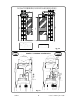
The position of the plastic condensate drain pipe is
shown in
Fig 5:1
Where possible an internal termination of the
Condensate discharge pipework should be used.
Installation pipework must be in plastic to a suitable
drain location with a gradient of 2.5° (45mm/ meter
run) minimum. If connected to another drainage
trap, an air break is required between the Heater
drain and that trap. (
See Fig.10:2). Internal runs
must be in a minimum of 19mm pipe. External runs
MUST be made in a minimum of 32mm pipe,
starting inside the building, and if possible insulated
to defer problems from freezing.
Whichever method is used it should be checked
during commissioning to prove there is a leakfree
working connection from the Heater to the drain. The
simplest way to do this is to carefully pour some
water into the Heater flue and check it emerges at
the drain.
The British Gas booklet “Guidance for the installa-
tion of Domestic Condensing Boilers” should also be
referred to.
5
SPACE HEATING
5:1 Typical Radiator System Design
General Principals
No special requirements are need for the selection
of radiators, normal sized radiators are acceptable.
The Manufacturer recommends using a programma-
ble room thermostat, alternatively a separate room
thermostat and timeswitch can be used.
The Heaters include a pump overrun device so it is
essential that there is an open circuit for water to
flow between the flow and return. An Automatic
Bypass is incorporated in the appliance which
should be sufficient for most system designs.
The Heater includes integral frost protection. If the
temperature approaches freezing it will first try and
use the heat in the pool by running the Pool Pump.
If this does not raise the temperature it will run the
Heater. It will do this even when turned to Off, and
can only be inhibited by removing the Permanent
Live supply to the Heater.
Thermostatic radiator valves can be used.
The Heater Pump is factory set at Speed 3 and
should not be alterered.
The Heater waterside is completely copper so all
good corrosion inhibitors are suitable. Inhibitor is not
required for Pool only applications.
The design temperature difference across the
Heater for optimum operating efficiency is 20°C. If
thermostatic valves or zone valves are used ensure
the minimum flow shown in the Technical Data on
page 1 is possible.
5:2 Electrical Connections
WARNING: The appliance MUST be
earthed.
All wiring for the Heater and system controls MUST
conform to I.E.E. Wiring Regulations, and work
should be tested using a suitable meter, for Earth
Continuity, Polarity, Short Circuit and Resistance to
Earth.
The supply must be through a common isolator, a
double pole 3A fused isolating switch with a contact
separation of 3mm minimum on both poles. The
cable used should be no less than 0.75mm
2
to
BS.6500 PVC, 3 core, and fixed ensuring the earth
connection is longer than the Live and Neutral.
Access to the Heater connections is made by
sliding out the bottom tray which is held by mag-
nets, removing the single screw retaining the
Electrical Tray then releasing the screws retaining
the Chassis Cover.
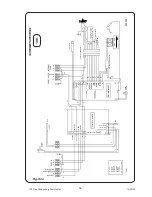
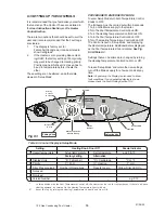
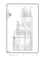
The Heater internal wiring is shown in
Fig.5:2a &
Fig. 5:2b.
Connections are made by push fit connectors
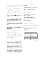
Connections are as follows :-
3 Way Terminal
4 Way Terminal
Earth
Pool Pump
Neutral
Neutral
Permanent Live
Heating Demand
Pool Demand
A link is factory fitted between the Permanent Live
and the Pool Demand and should be removed if a
separate switched supply is provided for Pool
Heating.
For systems using an external programmer, the
electrical wiring should follow the relevant control
manufacturer’s recommendations, with the switched
live from the controls returning to Pool Demand and/
or Heating Demand in the 4 way push-fit connector.
12
100 Gas Condensing Pool Heater
01/06/02