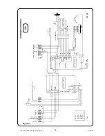


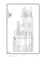


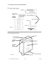


Fig. 7:2b
25
100 Gas Condensing Pool Heater
20/10/03
By using the flow charts basic problems can be identified.
If the particular fault cannot be immediately identified, follow the charts from beginning to end
Before commencing, always check that the Mains is ON and the system controls are calling for heat, the gas cock is open.
Test the electrical system for short circuit, polarity, and resistance before attempting any electrical fault finding.
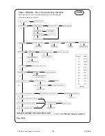
BOILER ACTION
Ensure Mains is ON.
Hot Water
required.
required.
Turn on any
Hot Water tap.
Ensure Clock/Thermostat
is set to call for heat.
Demand for heat
Fan and Pump start.
For HW Diverter Valve moves
to demand position.
Air Pressure switch
detects air flow.
Burner lights on
low flame.
Gas Valve opens for pilot.
Spark at electrode.
DHW: Burner to full rate.
CH: Low flame for 100 secs
then increases to full rate.
Flame modulates with heat demand.
Cycles ON and OFF if demand very low.
Demand Satisfied
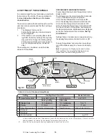
USER CONTROLS
Operation Sequence
FAULT FINDING
Fault causes excess
temperature
Overheat trips
'Lockout' neon illuminates
A 'Demand' LED illuminates
Burner & Fan stop
100W