


8
EXTREME ELECTRIC BUTTERFLY VALVE
6. INSTALLATION AND COMMISSIONING
Before starting the installation process, check that all the parts needed for the valve assembly are there, and that the materials,
connection type and nominal pressure are suitable for the installation.
For solvent or welded connections, ensure also that the parts to be connected are of the same material and that the correct solvent or
welding tools are used.
To install the valve, follow best installation practice recommendations provided on the Cepex website, paying specific attention to
thermal expansion and pipe alignment.
When filling the pipes with liquid, check that all the air has been purged from the system and that the initial pressure does not exceed
the nominal pressure of the valve, or of the system element with the lowest nominal pressure rating.
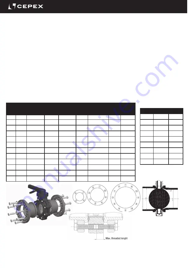
Valve assembly using standard ISO-DIN, ANSI, JIS and BS/E flanges. Flat gaskets are not needed in the socket couplings, as they are
incorporated in the valve itself. Observe the tightening sequence of the screws on the flanges (Fig. 6) and the maximum tightening
torque. All screws must be used in the flange in order to ensure proper operation of the valve.
The PP/PE sockets for butt welding must be chamfered as indicated in the diagram (Fig. 7) and table (T5.2), to ensure correct opening
and closing of the disc.
Install the valve once the sockets are solvent-bonded and dry, to avoid problems with the adhesive (entry of the latter into the valve).
Flanges must be well centred on the valve (pay special attention to measurements DN100-DN125 and DN200). Misalignment on
assembly could cause problems with the valve operation.
The threads of the screws and the inserts must be cleaned and lubricated in order to avoid seizing between the screw and the
insert.
The conditions of the installations and abience could need modifications in the installation standards.
An unnecessary over-torque will damage the flange.
D
DN
PN10
Screws (A2)
DIN (PN10)
inch
ANSI-150
Screws (A2)
ANSI-150
Insert
length
(mm)
Max. Threaded
lenght in both
sides L (mm)
Screws
Torque
(N·m)
Screws
Torque
(inch·lbs)
50
40
4xM16x2
1 1/2”
4xUNC 5/8
33
All
25
221
63
50
4xM16x2
2”
4xUNC 5/8
45
20
25
221
75
65
4xM16x2
2 1/2“
4xUNC 5/8
45
20
25
221
90
80
8xM16x2
3”
8xUNC 5/8
48
25
25
221
110
100
8xM16x2
4”
8xUNC 5/8
54
25
30
265
125
125
8xM16x2
64
25
35
310
140
125
8xM16x2
5”
8xUNC 3/4
64
25
35
310
160
150
8xM20x2,5
6”
8xUNC 3/4
70
25
40
354
200
200
8xM20x2,5
71
30
50
442
225
200
8xM20x2,5
8”
8xUNC 3/4
71
30
50
442
280
250
12xM20x2,5
10”
12xUNC 7/8
114
30
80
708
315
300
12xM20x2,5
12”
12xUNC 7/8
114
30
80
708
Screws and screw tightening torque
DN
D min.
x
40
31
30º
65
50.5
30º
80
70
30º
100
91.5
30º
125
113
30º
150
141
30º
200
191.5
20º
250
226
20º
300
296.5
20º
Fig. 4
Fig. 5
Fig. 6
Pipe and chamfer
measurements
PP/PE sockets
T 6.2
T 6.1
Recommended
installation