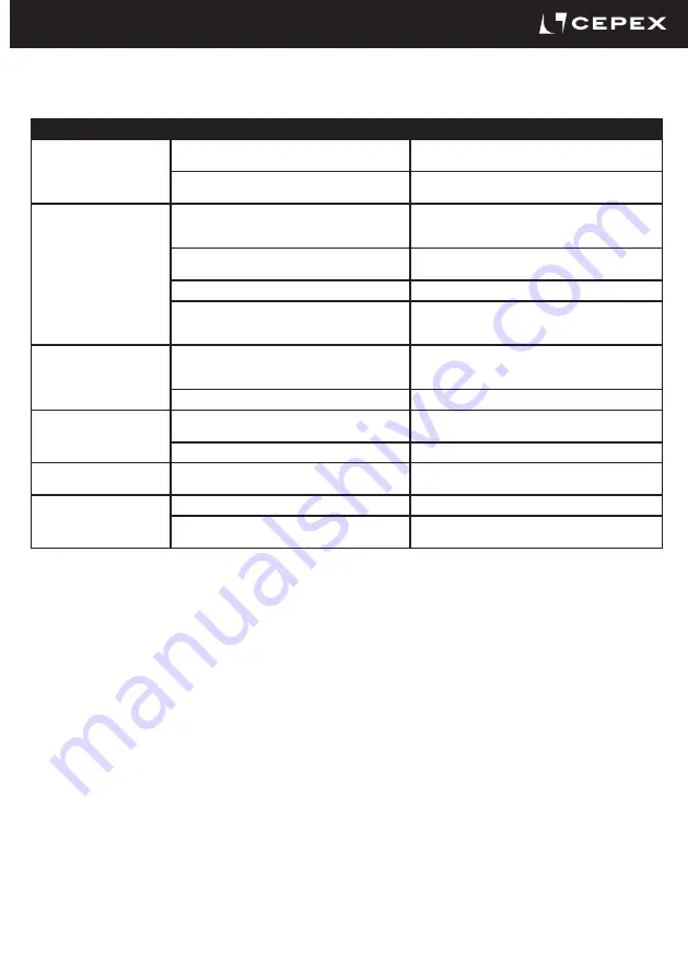
Cepex EXTREME ABS Series Installation And Maintenance Manual Download Page 11

11

10.  

TROUBLESHOOTING

T 9.1

FAULT

POSSIBLE CAUSE

FAULT CLEARANCE

The disc does not fully open 

or close.

The sockets were not correctly bevelled.

Disassemble the valve and bevel the sockets as indicated 

in table T6.2.

Foreign materials in the compartment (adhesive, etc.).

Disassemble the valve and check for obstructions in the 

disc and gasket contact area.

Excessive opening or closing 

torque.

The valve has been inactive for a long time.

Operate with an auxiliary release key (not the plastic 

handle). 

Disassemble the valve and lubricate the sealing gasket.

High temperatures or chemicals can cause damage to 

the gasket.

Check the chemical compatibility of the liquid with the 

disc and the working temperature. Replace the gasket.

Excessive flange torque.

Tighten flanges as indicated in table T5.1.

Misalignment between sockets and valve.

Disassemble the valve and reassemble with concentric 

alignment (observe the correct tightening sequence and 

torque).

The valve is not completely 

watertight in the sockets.

Misalignment between sockets and valve.

Disassemble the valve and reassemble with concentric 

alignment (observe the correct tightening sequence and 

torque).

Flange screws not tight enough.

Tighten flanges as indicated in table T6.1.

The valve is not completely 

watertight at the sealing 

gasket.

Inadequate chemical resistance.

Check compliance with the specifications in this 

document.

Temperature out of range.

Replace the gasket.

The  valve  does  not  open  or 

close.

Lack of current.

Check  power supply to the actuator.

The  valve  does  not  close 

completely.

The actuator stroke is not well adjusted to the valve.

Check adjustment limits according to the actuator manual.

The torque of the valve has increased above the 

calculated value.

Check the valve: obstructions in the disc or malfunction 

of the valve.

EXTREME ELECTRIC BUTTERFLY VALVE

Summary of Contents for EXTREME ABS Series

Page 1: ...EXTREME SERIES BUTTERFLY VALVES LUG type Electric actuator INSTALLATION AND MAINTENANCE MANUAL PVC U EPDM FPM CPVC EPDM FPM PPH EPDM FPM PVDF EPDM FPM ABS EPDM FPM 0045...

Page 2: ...teriales termopl sticos Meets the requirements established by the European Union for PRESSURE EQUIPMENT ac cording to Directive 2014 68 UE PED category II module A2 in accordance with the harmo nized...

Page 3: ...r close the manual valve control is not recommended Before carrying out any maintenance operations on the pipe or valve ensure that the system has been depressurised by releasing the pressure and empt...

Page 4: ...s of the valve body This allows them to be installed into a system using sets of bolts and no nuts The valve is installed between flanges using a separate set of bolts for each flange This setup permi...

Page 5: ...OM DN65 AISI 304 1 1 13 O ring EPDM FPM 2 4 14 Screw DIN 912 AISI 304 AISI 316 1 1 15 Handle PP GR 1 16 Washer AISI 304 AISI 316 1 17 Lever PP GR 1 18 Pin AISI 304 1 19 Left spring AISI 304 1 20 Right...

Page 6: ...e will cause irreparable damage to the device All valves are electrically and hydraulically tested in the factory Valves will always be replaced in the event of any justifiable claim For more technica...

Page 7: ...12 Valve design Flanged dimensions Valve connections Other connections Actuator coupling ISO 16136 2005 EN 558 1 ANSI B16 5 Class 150 JIS B2220 BS E EN 1090 1 ISO15494 ISO15493 ISO10931 EN ISO 5211 N...

Page 8: ...nd closing of the disc Install the valve once the sockets are solvent bonded and dry to avoid problems with the adhesive entry of the latter into the valve Flanges must be well centred on the valve pa...

Page 9: ...sources Actuators do not have fuses and incorrect voltages can cause irreparable damage to the device J J Characteristics Thermostat controlled temperature Incorporation of a thermostat controlled 4W...

Page 10: ...12 Tap on the shaft 6 with a rubber mallet until the bearing 4 is exposed from the bottom Fig 11 Once the bearing is out remove the shaft 6 turn it and re insert it Fig 12 from the bottom Tap again u...

Page 11: ...ockets and valve Disassemble the valve and reassemble with concentric alignment observe the correct tightening sequence and torque The valve is not completely watertight in the sockets Misalignment be...

Page 12: ...Av Ram n Ciurans 40 PI Congost P6 La Garriga BCN Spain Tel 34 93 870 42 08 www cepex com cepex cepex com COPYRIGHT CEPEX S A U ALL RIGHTS RESERVED CODE C584075MELXT Version 1 3 2020 01...

Reviews: