background image


38

For the FW700 and the FW3000 model, we suggest that you operate it with the air control slightly 
open (approximately 10%) to achieve an optimum efficiency.  Make sure that you have a good fire 
going and an adequate ember bed before you completely close the air control.  Use a chimney 
thermometer if necessary.  Closing the air control too soon will lower combustion efficiency and may 
cause the fire to die out.  
 
In all Century appliances the addition of a blower is highly recommended to maximize your unit’s 
efficiency. 
 

3.6 FAN (BLOWER) OPERATION 

 
If you have purchased and installed and optional fan (blower),  allow the stove to reach operating 
temperature (approximately one hour), before turning on the fan.  The increased airflow from the fan 
will cool the firebox and affect the start-up combustion efficiency if the fan is turned on too quick. 
 

CAUTION

:

 ENSURE THAT THE FAN

S  POWER CORD IS NOT IN CONTACT WITH ANY SURFACE OF THE TTOVE 

TO PREVENT ELECTRICAL SHOCK OR FIRE DAMAGE

.

 DO NOT RUN THE POWER CORD BENEATH THE STOVE

.


Summary of Contents for FW2470

Page 1: ...E MANUAL US ENVIRONMENTAL PROTECTION AGENCY PHASE II CERTIFIED WOOD STOVE Verified and tested following ULC S627 and UL 1482 Standards by STOVE BUILDER INTERNATIONAL INC 250 de Copenhague Saint Augustin de Desmaures Quebec Canada G3A 2H3 Tel 418 878 3040 Fax 418 878 3001 ...

Page 2: ... damage bodily injury or even death Consult your municipal building department or fire officials about restrictions and installation requirements in your area and the need to obtain a permit KEEP THIS INSTRUCTIONS MANUAL FOR FUTURE REFERENCE CAUTIONS HOT WHILE IN OPERATION KEEP CHILDREN CLOTHING AND FURNITURE AWAY CONTACT MAY CAUSE SKIN BURNS DO NOT USE CHEMICALS OR FLUIDS TO IGNITE THE FIRE DO NO...

Page 3: ...g masonry chimney 24 2 3 CHIMNEY CONNECTOR 27 2 4 DRAFT 29 2 5 OUTSIDE COMBUSTION AIR 29 2 6 THE ADVANTAGE OF INSTALLING A BLOWER FAN 31 SECTION 3 0 OPERATION 32 3 1 SAFETY INFORMATION 32 3 2 FUEL 34 3 2 1 The use of manufactured logs 35 3 2 2 Simple wood moisture test 35 3 3 NOTES ABOUT FIRST FIRING 35 3 4 LIGHTING A FIRE 36 3 5 MAINTAINING THE FIRE 37 3 6 FAN BLOWER OPERATION 38 SECTION 4 0 MAIN...

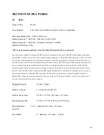
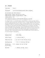
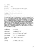
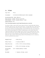
Page 4: ...3 SECTION 5 0 FEATURES 42 5 1 S244 42 5 2 FW2470 43 5 3 FW2700 44 5 4 FW3000 45 CENTURY HEATING LIMITED WARRANTY 47 ...

Page 5: ... SOURCES OR MODIFYING THE DIMENSIONAL SPECIFICATION OF COMPONENTS MAY RESULT IN HAZARDOUS CONDITIONS WHERE SUCH ACTION IS CONSIDERED THE MANUFACTURER SHOULD BE CONSULTED IN THE FIRST INSTANCE DO NOT CONNECT THIS UNIT TO ANY AIR DISTRIBUTION SYSTEM CRACKED AND BROKEN COMPONENTS e g GLASS PANELS OR CERAMIC TILES MAY RENDER THIS INSTALLATION UNSAFE A SOURCE OF FRESH AIR INTO THE ROOM OR SPACE HEATED ...

Page 6: ... 5 395mm 15 5 395mm 17 5 420mm 17 5 420mm 11 280mm 11 280mm 84 2 13m FW3000 15 380mm 15 380mm 26 660mm 26 660mm 12 305mm 12 305mm 84 2 13m Height from floor protection to ceiling You may decrease these clearances by installing heat radiation shields between the walls or the ceiling and the stove These heat radiation shields must be installed permanently and can include sheet metal a rigid non comb...

Page 7: ...tion shield the clearances mentioned on the stove certification plate may be reduced as stated in the following table TYPE OF PROTECTION Reducing Clearances With Shielding Sides and Rear Back Top Sheet metal a minimum of 0 024 0 61mm spaced out at least 1 25mm by non combustible spacers see graphic 2 67 50 Ceramic tiles or an equivalent non combustible material on fire proof supports spaced out at...

Page 8: ...tection B 500 mm 20 po minimum C 25 mm 1 po minimum D Between 25 mm 1 po and 75 mm 3 po E 75 mm 3 po minimum F 450 mm 18 po minimum 1 Wall shielding 2 Non combustible spacers 3 Ceiling shielding 4 Combustible wall 5 Ceiling 6 Heater side view 7 Heater top view ...

Page 9: ... 2 Non combustible spacer 3 Fire proof support 4 Ceramic tile or equivalent non combustible material _____________________________________________________________________________ Graphic 4 A 25 mm 1 po minimum 1 Combustible wall 2 Non combustible spacer 3 0 61 mm 0 024 sheet metal 4 Fire proof support 5 Ceramic tile or equivalent non combustible material ...

Page 10: ...9 Graphic 5 A 25 mm 1 po minimum 1 Combustible wall 2 Non combustible spacer 3 Brick Graphic 6 A 25 mm 1 po minimum 1 Combustible wall 2 Non combustible spacer 3 0 61 mm 0 024 sheet metal 4 Brick ...

Page 11: ...ease note that a floor protection is required with the pedestal models for spark and ash shielding but not for limiting floor temperatures from the radiant heat of the stove The stove was designed and safety tested so that without any protection the floor would not overheat Please refer to local building codes for suitable floor protection materials FRONT 18 300 mm SIDES 8 200 mm BACK 8 200 mm FIG...

Page 12: ...tor is a single pipe A double wall connector has two concentric pipes no insulation and is an air cooled connector 2 2 CHIMNEY CAUTION DO NOT fill any framed space around the factory built chimney with insulation or any other material Insulation placed in this area could cause adjacent combustibles to overheat Do not use makeshift compromises during installation as they may be safety hazards and a...

Page 13: ...The chimney must rise above the roof at least 3 0 9 mm from the uppermost point of contact See Figure 2 2 The chimney must exceed any part of the building or other obstruction within a 10 3 04 m distance by a height of at least 2 0 6 m See Figure 2 2 The minimum overall height of the chimney system measured from the stove top to the exterior termination cap of the chimney should be at least 12 3 6...

Page 14: ...e sold at many North American retailers of wood stoves and related heating accessories Wall support system If your chimney must rise along an outside wall you need to connect it to your stove through an adjacent wall For this type of installation the following items are normally required Chimney Suitable lengths of chimney enough to go up to your roof An adjustable wall support A wall thimble An a...

Page 15: ...14 Stove pipe An adequate number of stove pipe sections A 90o elbow Typical installation through the wall FIGURE 2 2 1 A Typical installation through the wall ...

Page 16: ...to locate the studs Use a spoke saw or jig saw to cut a hole remembering that you need to maintain a clearance of 2 inches between the chimney and any combustible materials For concrete walls cut a hole slightly larger than the outer diameter of the chimney 2 Once the opening completed you need to frame in the area to allow for the installation of a wall thimble A wall thimble is not required for ...

Page 17: ...s to the stove pipe 5 You can now install the wall support Simply slide the wall support up to the tee ensuring that the adapter on the support engages with the female coupler on the bottom of the tee When the wall support is level and properly positioned you can use lag bolts to secure it into the wall studs To complete the installation install an insulated tee plug below the wall support ...

Page 18: ...be installed through your soffit install a roof flashing above and finishing plate below where the roof is cut Consult the following section called CEILING SUPPORT SYSTEM for more details 7 Authorities require that the chimney extend not less than 3 feet above the highest point where it passes through the roof of a building and not less than 2 feet above any portion of the building within 10 feet ...

Page 19: ...ling support system If your chimney must rise inside the house and go through the ceiling you need to connect it to your stove at the ceiling level For this type of installation the following items are normally required Chimney An adequate number of chimney sections enough to go up to your roof A ceiling support kit with stove pipe adapter An attic insulation shield A roof flashing kit A chimney c...

Page 20: ...19 Typical installation through the ceiling FIGURE 2 2 1 B Typical Installation Through the Ceiling ...

Page 21: ... go through the ceiling use a spoke saw or power jig saw to cut a hole remembering that you need a minimum 2 inch clearance between the chimney and any combustible materials Depending on whether you have a one or two story structure you will need to cut a matching hole through the floor of the attic or second floor living space 2 Before you install the ceiling support you need to frame the area 3 ...

Page 22: ... height of about 2 feet below the next ceiling level An attic insulation shield must be installed where a chimney passes from a lower living space into an upper living space or attic space It is designed to keep insulation materials away from the chimney A second attic insulation shield must be installed if your chimney passes from a lower living space into an upper living space As wee you must en...

Page 23: ...our chimney pipe and goes under your shingles Once you have done that check that everything is plumb and nail the flashing into the roof deck Seal the joint between the shingles and the plate with silicone 8 Next slide the storm collar down the chimney until it contacts the flashing Tighten the nut and bolt and seal the collar to the chimney with a waterproof non combustible silicone sealant Final...

Page 24: ...ect your chimney to your stove Simply install the inter connecting stove pipe between the stove pipe adapter and the stove You can follow the instructions in the following section section 2 3 of this manual called CHIMNEY CONNECTOR ...

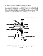
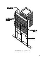
Page 25: ...y built thimble on construct your own brick thimble If you are using a masonry chimney it is important that it be built in compliance with the specifications of the Building Code in your region It must normally be lined with fire clay bricks metal or clay tiles sealed together with fire cement Round flues are the most efficient FIGURE 2 2 2 A Typical Installation Through an Existing Masonry Chimne...

Page 26: ...25 FIGURE 2 2 2 B Factory Built Thimble ...

Page 27: ...26 FIGURE 2 2 2 C Brick Thimble ...

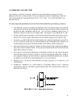
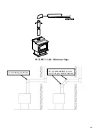
Page 28: ...od draft the total horizontal length of the connector should never exceed 8 to 10 2 4 to 3 04 m In the case of vertical installation the total length of the connector can be much longer and connected without problem to the chimney at the ceiling level There should never be more than two 90 degrees elbows in the whole connector and chimney system Never start with a 90o elbow Always go up vertically...

Page 29: ...28 FIGURE 2 3 B Minimum Slope Avoid 90 degree eblows We recommend that you use two 45 degree elbows instead ...

Page 30: ...in the vertical chimney connector to help reduce excessive draft 2 5 OUTSIDE COMBUSTION AIR It is recommended to install 3 76mm outside air intake in the room where the stove is located or nearby The following are signs that a fresh air kit may be required Your stove does not draw steadily smoke rollouts occur wood burns poorly or back draft occurs whether or not there is combustion present Existi...

Page 31: ...e ring A as shown below Ring A is a small piece of metal held by micro joints located inside the 3 76mm spigot on the middle of the back pedestal shield 2 Put the back pedestal shield in place using the 4 screws 3 Connect a flexible insulated pipe to the 3 76mm spigot on the back pedestal shield Secure the pipe using pipe clamps The complete fresh air kit is available at your Century dealer ...

Page 32: ...edistribute into a room the heat trapped at the back of your stove By forcing hot air toward the front the blower enables you to extend the radiation and convection power of your stove You can purchase this option through your E P A Century dealer Make sure you specify the correct part number AC02050 Installation instructions are supplied with the blower ...

Page 33: ...ND FURNITURE AWAY CONTACT MAY CAUSE SKIN BURNS WEAR GLOVES TO OPERATE YOUR STOVE CAUTION THIS APPLIANCE SHOULD BE MAINTAINED AND OPERATED AT ALL TIMES IN ACCORDANCE WITH THESE INSTRUCTIONS THE USE OF SOME TYPES OF PRESERVATIVE TREATED WOOD AS A FUEL CAN BE HAZARDOUS 3 1 SAFETY INFORMATION These stoves are designed for safe operation WHEN BURNING WOOD ONLY Altering or modifying the unit or installa...

Page 34: ...thermometer If you are using a probe thermometer make sure that the temperature does not exceed 900o F 482o C If you are using a magnetic thermometer make sure that the temperature does not exceed 475o F 246o C If the door handle of the stove becomes excessively hot to the touch consider this to be an indication of over firing Over firing can result in a safety hazard and can permanently damage th...

Page 35: ...ideal Dry seasoned cord wood can be distinguished from green wood by the cracks at each end of the logs Wet or green wood will tend to cause the fire to smoulder producing large amounts of creosote Creosote buildup could result in a chimney fire This wood will also prove difficult to keep burning properly and fires will tend to go out Green wood produces very little heat and sometimes causes custo...

Page 36: ...logs into your stove like you would with regular cord wood Start with one log and gradually increase the load to 2 or 3 logs and see how your stove reacts Use a chimney flue thermometer and make sure that temperatures remain within the normal operating range 3 2 2 Simple wood moisture test Add one large piece of wood to the top of an established fire If it starts to burn on three sides within one ...

Page 37: ...is well established Once the firebox is hot the air control can be partially closed After 30 minutes to one hour you can close the air control completely In order to have the best indication of when you should close the air control completely to operate your stove the most efficiently use a chimney flue thermometer If you are using a probe thermometer you can close the air control completely when ...

Page 38: ...ox and a minimum of two large pieces of seasoned fuel are added Combustion efficiency is largely related to establishing a hot ember bed and hot firebox temperatures The quicker the stove and chimney flue get up to normal operating temperatures the better A small intense fire is preferred to a large smouldering fire both to improve combustion efficiency and to reduce the amount of creosote build u...

Page 39: ...ut In all Century appliances the addition of a blower is highly recommended to maximize your unit s efficiency 3 6 FAN BLOWER OPERATION If you have purchased and installed and optional fan blower allow the stove to reach operating temperature approximately one hour before turning on the fan The increased airflow from the fan will cool the firebox and affect the start up combustion efficiency if th...

Page 40: ...t use the stove if the glass is broken If the glass on your stove breaks replace only with a ROBAX glass 5mm thick supplied by your E P A Century dealer Never use a substitute material To replace the glass remove the screws retaining the glass retainers inside the door Remove the mouldings and replace the damaged piece with a new one Perform the procedure backwards after replacing When replacing t...

Page 41: ...wer using the following instructions Make sure the fire is out and the stove is cold Lift the ash dump plug in the center of the firebox by hooking the poker through the loop on the cover and lifting up Push the ashes through the hole and leave an ash bed of approximately 1 deep on the firebox bottom to help maintain a hot ember bed Clear the ashes from the area where the ash dump plug normally si...

Page 42: ...g fire As a result creosote residues accumulate on the chimney When ignited this creosote makes an extremely hot fire which could be hazardous Your E P A Century stove has been designed to reduce the amount of creosote produced Even so the chimney and any chimney connector should be inspected at least once every two months during the heating season to determine if a creosote build up has occurred ...

Page 43: ...d during emissions testing The EPA test procedure requires that a special type of wood be used and positioned inside the firebox in a manner that does not represent the way the firebox volume would normally be utilized using seasoned cordwood The EPA test load is typically much smaller Hence the BTU as per the EPA label is reduced The BTU output that should be considered by a normal user is the on...

Page 44: ...ions testing The EPA test procedure requires that a special type of wood be used and positioned inside the firebox in a manner that does not represent the way the firebox volume would normally be utilized using seasoned cordwood The EPA test load is typically much smaller Hence the BTU as per the EPA label is reduced The BTU output that should be considered by a normal user is the one we advertise...

Page 45: ...issions testing The EPA test procedure requires that a special type of wood be used and positioned inside the firebox in a manner that does not represent the way the firebox volume would normally be utilized using seasoned cordwood The EPA test load is typically much smaller Hence the BTU as per the EPA label is reduced The BTU output that should be considered by a normal user is the one we advert...

Page 46: ...missions testing The EPA test procedure requires that a special type of wood be used and positioned inside the firebox in a manner that does not represent the way the firebox volume would normally be utilized using seasoned cordwood The EPA test load is typically much smaller Hence the BTU as per the EPA label is reduced The BTU output that should be considered by a normal user is the one we adver...

Page 47: ...46 ...
Page 48: ...st not exceed the wholesale price of the replacement part All parts and labour costs covered by this warranty are limited according to the table below The manufacturer at its discretion may decide to repair or replace any part or unit after inspection and investigation of the defect The manufacturer may at its discretion fully discharge all obligations with respect to this warranty by refunding th...

Reviews: