


page 35
www.centsys.com
7.1 Traffic Light Status
The traffic light feature is enabled or disabled in this menu. By default, the feature is
enabled in all current operating profiles (ZA, CE, UL325)
1
. In the event that a traffic light
feature is not needed based on specific site requirements, the feature may be turned
OFF via this menu. If the feature is turned OFF, the physical output associated with the
feature (configured in Menu 7.2) will be driven to, and remain in, an inactive state.
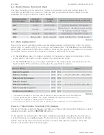
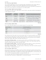
7.2 Traffic Light Function Output
The logic signalling of the feature is routed to a physical controller output based on
the setting specified in this menu. There are four physical controller outputs that are
available for output routing. The outputs are listed in the table below, along with the
relevant electrical characteristics of the respective outputs:
7.3 Trigger Level
Specifies the arc angle that triggers the transition of the relevant output signal from an
inactive state to an active state. From 0 degrees up to but excluding the specified angle
2
,
the output is always inactive (normally-open, or floating depending on the configured
output used). From the specified angle through to 90 degrees inclusively, the output is
active (normally-closed, or active low depending on the configured output used).
The Trigger Level is specified as an arc angle, measured in degrees. The angle is
measured with respect to the horizontal (0 degrees), increasing in the opening or raising
direction of the barrier.
1. Please note that it should not be taken for granted that the traffic light feature will always be enabled by default.
Future statutory requirements may dictate that this feature is not enabled by default in one or other of the
operating profiles.
2. For the purposes of clarity, in the event that the Trigger Level is set to 0 degrees, the output will transition to the
active state as soon as the barrier transitions to the RAISING state. In other words, the traffic light will go green as
soon as a raising command is executed by the
SECTOR II
.
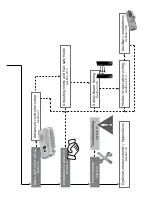
Menu 8 - Barrier Status
The
S-SERIES
controller provides a feature to indicate a barrier operating state (e.g.
Lowered, Raising, Raised, etc), or set of states, to an external device. The purpose of this
is to signal the operating condition of the
SECTOR II
barrier to some external piece of
equipment (e.g. Interlocked access control equipment such as another barrier or a gate
operator, programmable logic controllers, alarm systems, etc).
8.1 Barrier Status
The Barrier Status Indication feature can be turned ON or OFF, independent of any other
settings associated with the feature. If the feature is turned OFF, the physical output
associated with the feature (configured in Menu 8.2) will be driven to, and remain in, an
inactive state.
Output setting
on controller
Output
Description
Output
Type
Electrical Switch Characteristics
RLY
Relay
Dry Contact
24V DC/250V AC, 2A contact
XIO
Aux IO
Open Drain
Open Drain – 3A sink current, with a
3V floating terminal Voltage.
AUX
Aux Out
Open Drain
Open Drain – 3A sink current
LED
Status LED
Open Collector
Open Collector 5V – 50mA Source
TABLE 3
ADVANCED CONTROLLER SETUP
SECTION 7
Summary of Contents for SECTOR II
Page 82: ...page 82 www centsys com Notes...
Page 83: ...page 83 www centsys com Notes...


