Page 7
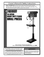
For technical questions, please call 1-888-866-5797.
Item 43389
S
AFET
y
Op
ERA
TION
M
AINTENAN
c
E
S
ETU
p
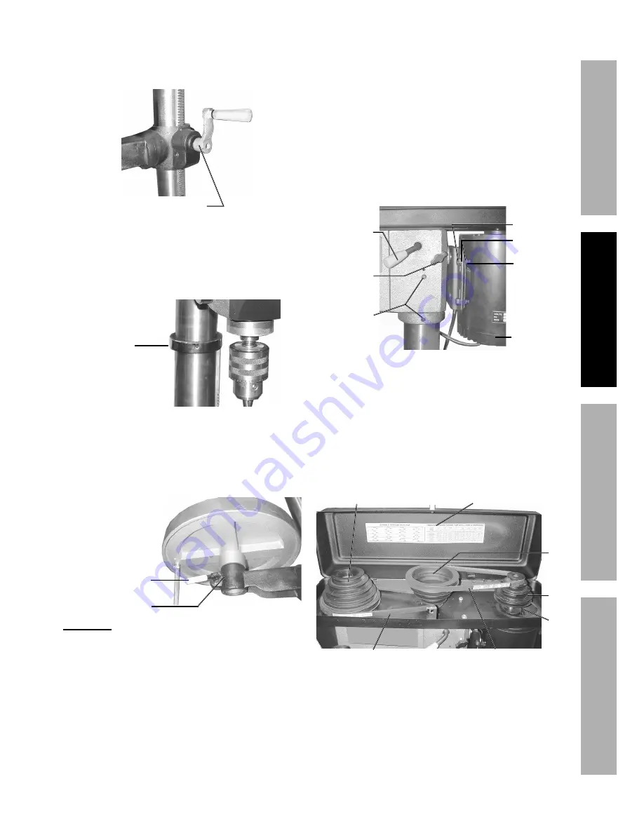
4. Mount the
Table crank
(B4) onto the right side of
the Table Support.
Tighten with the Hex Key. The set screw must be
tightened against the flat portion of the screw shaft.
Table Crank (B4)
5. Verify that the
column collar
(B2) is square to
the Column Tube and that the set screw is secure
(but not overtightened).
The Column Collar should be positioned so that
its rack will slide freely in the collar when the
Table (B6) is rotated around the Column Tube.
Column
Collar (B2)
6. Loosen the Table Clamp (B7) and insert the
Table
pivot into the Table Arm (B9).
It may be necessary to pry open the Table
Arm opening with a large screwdriver since
it is meant to be a tight fit. With the Table
in place, retighten the Table Clamp.
Table Clamp (B7)
Table Arm (B9)
cAUTION!
Avoid injuries. The next step involves
lifting the Head Assembly onto the Column Tube.
The Head Assembly weighs about 55 lb.
Have someone help you lift this assembly into place.
7. Using two people, lift the
Head Assembly
up and
onto the Column Tube (B14).
It should slide down on the Column Tube
as far as it will go. Align it so that it faces
straight forward, inline with the Base.
8. Screw in two Set Screws (2), into each side of
the Head (28) and tighten with the Hex Key.
9. Mount the
Motor
(43) onto the Head Assembly.
a. Place a Washer (39) on each of
four Machine Screws (38)
b. Insert Machine Screws into the Motor Mount (40)
(from left to right as shown above).
c. Position the Motor base slots
over the Machine Screws.
d. Place a Washer (39) and Nut (42) on each
Machine Screw (38). Hand tighten.
e. Position the Motor shaft at the center
of the Pulley Guard (A8).
Set
Screws
(2)
Head Assembly
Column Tube
Motor (43)
Machine
Screw (38)
Washer (39)
Nut (42)
Belt
Tension
Handle (3)
Motor
Adjusting
Knob (1)
10. Install the
Motor pulley
(A11).
a. Slide the Motor Pulley onto the Motor shaft.
b. Line up the flat notch on the shaft
with flat notch on the pulley.
c. The pulley should not touch the
lower Pulley Guard (A8).
d. Tighten the Motor Pulley onto the shaft
using the Hex Key and Set Screw (A10).
Motor
Pulley
(A11)
Set
Screw
(A10)
Speed-Belt Chart
Spindle Pulley (A6)
Center
Pulley
(A15)
V-belt (A17)
V-belt (A4)
11. Adjust the height of the Motor Pulley.
a. Lay a straight edge across the two pulleys.
b. Push the Motor up until the top of the
pulleys align. Hold Motor in place.
c. Using a wrench, tighten four Nuts
(42) supporting the Motor.
d. Turn the Motor Adjusting Knob (1)
counterclockwise to release belt tension.


