background image

G

ENERAL SPECIFICATIONS


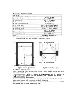
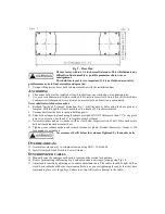
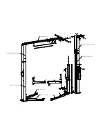
See Figure 1 

A

      Rise Height 

(Screw Pads Highest Position)


78 

1/8

(1985mm) 

B


Column Height 

151 

3/16

(3840mm) 

C

    Overall Width 

131 

1/2

(3340mm) 

D

    Drive-thru Clearance 

99 

3/8

(2524mm) 

E

    Floor to Overhead Switch 


144

(3660mm) 

F

    Short Arm Reach 

28 

1/4

-41 

3/8

(730-1050mm) 

G

    Long Arm Reach 

34 

3/8

-55 

1/8

(874-1400mm) 

H

    Screw Pad Height 

3/8

-7 

1/4

(136-185mm) 

K

    Inside of Columns 

109 

7/8

(2790mm) 

* Maximum Capacity 

10000LBS(4545kg) 

Ceiling Height Required 

152 

3/16

(3865mm) 

Motor 


2HP, Single Phase, 60Hz, 220V


*      Lift capacity ratings are based on loads equally distributed on all four arms. 
**  Lifting and lowering speeds may vary depending on weight of vehicle. 


12

 Min. To Nearest Obstruction   


12

 Min. To Nearest Obstruction


Fig 1a- General Specification                      Fig 1b- Service Bay Layout 

V

ERTICAL CLEARANCE   

Check the height of the area where the lift is to be installed. Clearance should be calculated based on the 
full raised height of the lift. 


Failure  by  purchaser  to  provide  adequate  clearance  could  result  in 

unsatisfactory lift performance, property damage, or personal injury.


F

LOORING 

Be  certain  you  have  the  proper  concrete  floor  to  properly  handle  the  loaded  lift.  Floor  should  be  in 
generally good condition with no large cracks, spalling or deterioration. 

Minimum requirements for concrete are 4 inches minimum depth, with steel reinforcement, 3500 
PSI, cured for 28 days per local commercial practice.   


Summary of Contents for 94780

Page 1: ...10000LBS 2 POST LIFT Model 94780 INSTALLATION OPERATION MAINTENANCE MANUAL IMPORTANT READ THIS MANUAL COMPLETELY BEFORE INSTALLING or OPERATING LIFT...

Page 2: ...lowering speeds may vary depending on weight of vehicle 12 Min To Nearest Obstruction 12 Min To Nearest Obstruction Fig 1a General Specification Fig 1b Service Bay Layout VERTICAL CLEARANCE Check the...

Page 3: ...REMENTS For lift installation and operation for single phase units it is necessary to have a dedicated circuit with a 25 amp circuit breaker or time delay fuse SAFETY NOTICES AND DECALS For your safet...

Page 4: ...sion 1 Power Lock Cover 1 Idler Column Extension 1 Idler Lock Cover 1 Overhead Ass y 1 Hardware Box 1 Rear Arm Ass y 2 Front Arm Ass y 2 INSTALLATION IMPORTANT Always wear safety glasses while install...

Page 5: ...r holding power 10 Shim both columns to plumb using the shims provided DO NOT shim more than 1 2 at any given point Use a level no less than 24 in length to plumb columns 11 Assemble washer and nut to...

Page 6: ...eal without damage to the fitting follow this procedure for each hose connection Screw flared fitting on finger tight Rotate flared fitting 1 1 2 hex flats 90 deg Back the flared fitting off one full...

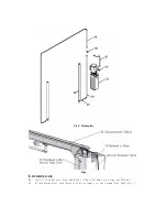
Page 7: ...Fig 5 Hydraulics Fig 6 LOCK RELEASE 23 Install Lock Release Stud and Knob to Power Column Lock using one M10 nut 24 Attach Mechanical Lock Release Cable Assembly to two Column Lock Pawl Fig 7...

Page 8: ...USTMENTS 29 Lower the lift to the floor and raise the lift approximately one foot 30 Start with Idler side first Slowly and carefully loosen the bleed plug on top of the cylinder just enough to allow...

Page 9: ...loyer shall insure that the lift inspector and maintenance personnel are qualified and that they are adequately trained in these procedures The employer shall maintain these periodic inspection and ma...

Page 10: ...issing or damaged See Installation instructions page 3 Daily 1 Keep lift components clean 2 Check for loose or broken parts 3 Check hydraulic system for fluid leaks 4 Check adapters for damage or exce...

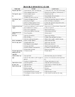
Page 11: ...hose 2 Defect in fitting 2 Tighten fitting and replace if necessary Fluid Leak 3 Defect in cylinder packing seals 3 Repack seals or replace cylinder if necessary Fluid is contaminated 1 Water or forei...

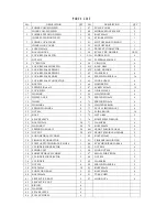
Page 12: ...WASHER 2 69 LIMITED BOLT 4 18 WHEEL AXES 4 70 SPRING PIN 4x24 4 19 WHEEL 4 71 SPRING PIN 4x30 4 20 WASHER 6 8 72 LIMITED SPRING 4 21 SPRING WASHER 6 8 73 LEVEL LIMITED BOLT 4 22 NUT M6 9 74 SLIDE BLOC...

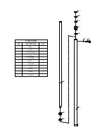
Page 13: ...1 RAM 2 1 RING RAM HEADER GUIDE RING CYLINDER BOLT WASHER O RING COVER O RING O RING 1 1 1 1 1 1 1 1 3 4 5 6 7 8 9 10 11 1 1 PARTS LIST NO DESCRIPTION QTY b1 b2 b11 b9 b8 b7 b6 b5 b3 b4 b10...

Page 14: ...4 2 28 27 26 25 18 19 20 21 22 8 17 16 15 14 13 12 6 7 5 9 11 10 8 3 1...

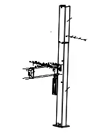
Page 15: ...8 42 41 40 21 20 22 20 2122 54 38 39 POWER COLUMN EXTENSION POWER COLUMN ASSY 33 82 26 27 69 70 71 72 73 66 67 64 68 62C 64 63 65 78 77 76 46 80C REAR ARM ASSY 92 IDLER COLUMN ASSY IDLER COLUMN EXTENS...

Page 16: ...you This warranty is expressly in lieu of all other warranties express or implied including the warranties of merchantability and fitness To take advantage of this warranty the product or part must b...

Reviews: