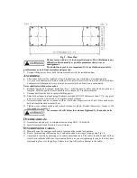
35.
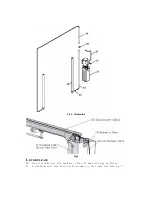
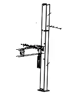
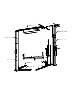
Lower lift to the floor. Pull and release lock release handle while watching idler column lock.
Adjust threaded sleeve cable adjuster nuts until idler column lock disengages and engages fully.
When properly adjusted, the idler column lock should just come to rest against the back of the
column when engaged and fully out against the tab when disengaged.
IMPORTANT
: IF IDLER SIDE LOCK PAWL DOES NOT FULLY DISENGAGE, DAMAGE
MAY RESULT TO IDLER SIDE CARRIAGE AND OR CABLE SYNCHRONIZING SYSTEM.
36.
Tighten and trim wire ties.
37.
Snap lock cover over each lock assembly.
O
PERATION PROCEDURE
S
AFETY NOTICES AND DECALS
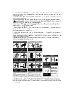
This product is furnished with graphic safety warning labels, which are reproduced on page 3 of
these instructions. Do not remove or deface these warning labels, or allow them to be removed or
defaced. For your safety, and the safety of others, read and understand all of the safety notices and
decals included.
O
WNER/EMPLOYER RESPONSIBILITIES
The owner/employer shall
make sure that all lift operators are qualified and trained in the safe use and
operation of the lift in accordance with the manufacturer
’
s operating instructions. They also shall
display the lift manufacturer
’
s operating instructions and maintenance schedule in a conspicuous
location and area, convenient to the operator.
The owner/employer shall
establish procedures to periodically inspect and maintain the lift in
accordance with the lift manufacturer
’
s suggestions. The employer shall insure that the lift inspector and
maintenance personnel are qualified and that they are adequately trained in these procedures. The
employer shall maintain these periodic inspection and maintenance records.
L
IFTING A VEHICLE
1)
Insure that the lifting arms are parked, out to full drive thru position.
2)
Position the vehicle in the service bay so that the vehicle
’
s center of gravity is on a line between the
two columns, and so the vehicle is centered between the two columns.
DO NOT EXCEED 2500 POUNDS PER ARM.
DO NOT ATTEMPT TO LIFT THE VEHICLE WITH ONLY TWO ARMS, AS THIS WILL
VOID THE WARRANTY
INSURE THAT THE HIGHEST POINT ON THE VEHICLE WILL CONTACT THE
OVERHEAD LIMIT SWITCH BAR
DO NOT PLACE THE VEHICLE IN THE SERVICE BAY BACKWARDS.
3)
Position the arms and adapters so all four pads contact the vehicle simultaneously.
The vehicle should remain level during lifting.
4)
Raise the lift until all four wheels are off the ground. Test the stability of the vehicle by attempting
to rock the vehicle. Check adapters for secure contact with vehicle lift points. If the vehicle seems
unstable, lower the lift and readjust the arms. If the vehicle is stable, raise the vehicle to a height a
few inches above the desired working height.
5)
Lower the vehicle until the safety latches on both columns engage. The vehicle should remain level
when both latches are engaged. If one side engages and the other continues to descend, stop
lowering the vehicle, raise it several inches, and try again to engage both latches.
Always lower lift into locks before entering the area beneath the vehicle.
Always use safety stands when removing or installing heavy components.

