


CenterVue
COMPASS Operating Manual
Pag. 32 di 53
Fig. 27
– Patient List in Remote Viewer
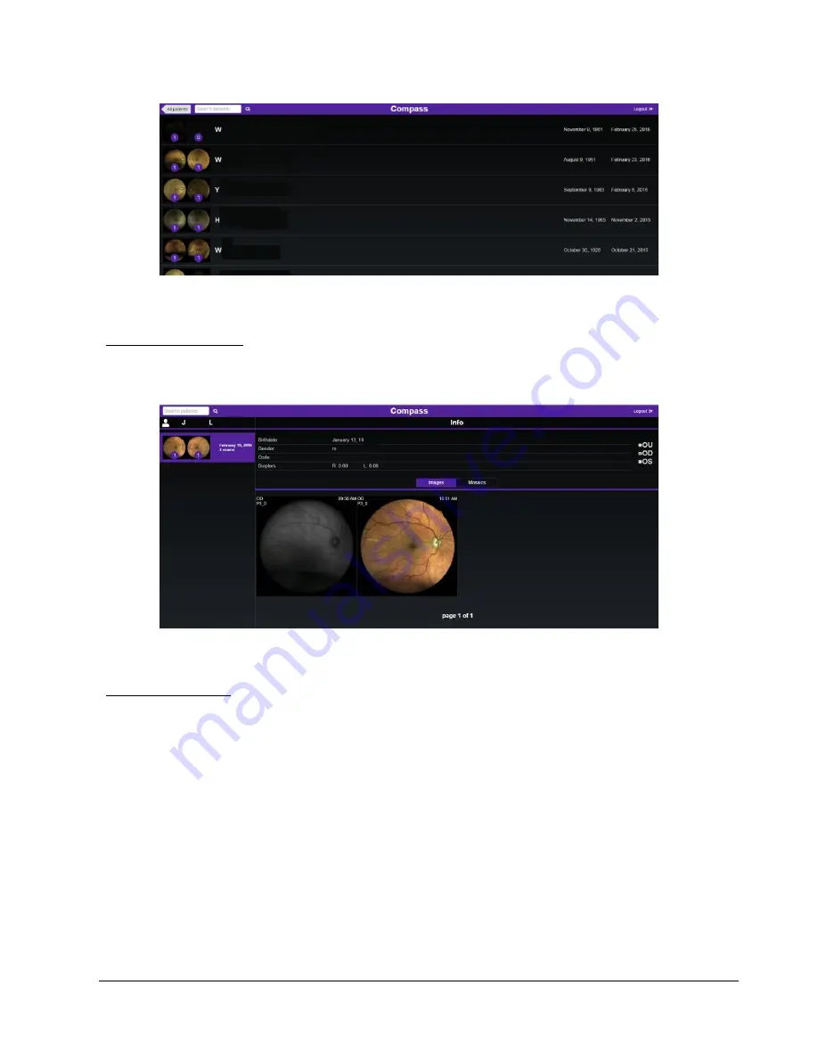
Patient Record screen
This screen allows access to individual images.
Click on the desired image to enter the
Single Image review
screen (see Fig. 29).
Fig. 28
– Patient Record screen in Remote Viewer
Exam review screen
The following commands are available in this screen:
1. Go back to Patient Record Screen
2. Logout
3. Displays patient related information (full name, date of birth, gender, code) and a thumbnail
view of all exams available for this patient (date and time of acquisition, eye, average pupil
size, exam type). Command is also used to compare the currently displayed image with any
other image in the list click on the corresponding Compare button: see Dual Image Review
screen (see Fig. 30)
4. Displays all exam related information (date and time of acquisition, eye, exam type,
threshold strategy, focus index, average pupil size)
5. Shows red-free version of color image
6. Allows to save the corresponding image (jpg), or test report (pdf), or progression report
(pdf, if available) on the local memory


