


43
Tube Flaring
First remove the caps from tube ends and check the edges. These
should be smooth, perfectly round and without burrs. If the section
gets out of round after cutting, use a gage mandrel. Insert the mandrel
into the tube and turn to round out the circumference.
Thoroughly straighten the tube walls for 5 cm from the edge, and then
flare the tube end to match it to the intake/outlet port and create a
sealed system. Proper performance of this operation is very important
as the system should be hermetically tight. This will the recharge time
after which the system will require recharging.
Hold the tube with the end down during flaring, so that copper particles
fall down and do not get into the tube. Clamp the tube in the holder
with a 2mm protruding end. Tighten the clamp, insert the flaring cone
and screw it on, applying deliberate force. The flaring is complete
when the cone will not go any further. Repeat the procedure on the
other tube end, then on the other tube.
If you have not flared tubes before, we recommend training on scrap
pieces of tube. The resulting tube edge should be smooth, with a
straight and uniform lip.
Connection to the Units
Align the flared tube end with the relevant outlet, screw the nut on.
Never use any additional gaskets, sealants, etc. Use special tubes
made of high quality copper, providing a proper seal without additional
accessories.
Apply serious force (Table 2).
Table 2
Tube size
(mm)
Torque
(Nm)
φ 6.35 (1/4”)
15~19
φ 9.52 (3/8”)
35~40
φ 12.70 (1/2”)
50~60
φ 15.88 (5/8”)
62~76
φ 19.05 (3/4”)
98~120
Only this way the copper will compress and seal around the nozzle,
making the connection practically gas tight. Always use a torque
wrench set to the right torque and always hold the indoor unit nozzle
with another wrench (see Fig. 12 of the Appendix).
Connect the pipeline to the outdoor unit using the same method.
After connecting the pipelines perform a full tightness test of the
connections.
VACUUM TESTING
ATTENTION!
Moist air in the cooling system can cause compressor malfunctions.
Moist outdoor air fills the copper tubes during installation. It will
penetrate into the system if it is not removed. This will cause the
compressor to work with a higher load and to overheat.
Moisture also negatively affects the functionality of the air conditioner.
The Freon refrigerant used in the AC contains a certain amount of oil
to lubricate the internal components. The oil is hygroscopic and, when
saturated with water, it will lubricate the components less effectively,
which will accelerate wear.
Air can be removed from the system using a vacuum pump.
For this operation you will need a vacuum pump, a high-pressure tube
and a group of two pressure gage: a high pressure and a low pressure
one (see Fig.13 of the Appendix).
Without opening the control valve vents connect the hose from the
vacuum pump to the intake check valve and turn the equipment on.
It should operate for 15 to 30 minutes during which all air, vapors and
residual nitrogen will be extracted.
After that turn the vacuum pump off, close the pump valve, but leave
it connected for another 15 to 20 minutes. Observe the pressure gage
readings during this time. If the system is tight the pressure gage
readings will not change. If the pressure gage hands move – there
is a leak and it will have to be repaired. The leak can be located with
soap suds, leaky connections can be tightened (the problem is usually
related to the copper tube connection to the unit outlets).
If the system is tight, with the pump hose still connected fully pen
the valve at the bottom. Sounds will be heard in the pipes: the Freon
is filling the system. Then quickly unscrew the vacuum pump hose –
some frozen Freon may escape from the valve (wear protective gloves
to prevent frostbite). Now fully open the top valve (where the thinner
tube is connected).
Air conditioned installation is now completed.
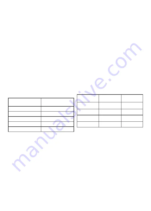
REFRIGERANT RECHARGING
If the pipeline length exceeds 5 meters, the system will have to be
recharged with refrigerant in accordance with Table 3.
Table 3
Gas
Liquid
Additional
Refrigerant
φ 9.52х0.75 mm
φ 6.35х0.75 mm
0.02 kg/m
φ 12.70х1,00 mm
φ 6.35х0.75 mm
0.02 kg/m
φ 15.88х1,00 mm
φ 9.52х0.75 mm
0.03 kg/m
φ 19.05х1,00 mm
φ 9.52х0.75 mm
0.03 kg/m
ERROR CODE TABLE ON PAGE 54!


