Cembre B35-50MD Operation And Maintenance Manual Download Page 6

6

ENGLISH

2.4)  Release of dies

Press the pressure release button (9), the ram will retract and open the dies.

2.5) Head rotation

For ease of operation the tool head can rotate through 180°, allowing the operator to work  in the 
most comfortable position.
Warning: do not attempt to rotate the head when the hydraulic circuit is pressurised.

2.6)  Replacement of dies

To replace the dies, open the head and extract them from their seats.
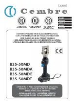
2.7) Battery status


(Ref. to Fig. 3)


The battery is equipped with LED indicators that indicate the remaining battery life at any time by 
pressing the adjacent button (P). 
4 LEDs illuminated: Fully charged
2 LEDs illuminated: 50 % capacity
1 LED  fl ashing: Minimum charge, replace the battery

2.8)  Insertion/replacement of battery

To replace the battery, remove it by pressing the release button (15) (Ref. to Fig.5 page 24), then 
insert the new battery, sliding it into the guides until it locks.

3.   WARNING

Before starting work on electrical equipment, please ensure that either there are no live parts in 
the immediate working area or that precautions are taken for working near live parts in accordance 
with EN50110-1.

     D

O


NOT


USE


THIS


TOOL


ON


OR


NEAR


ENERGIZED


CONDUCTORS


WITHOUT


PROPER


PERSONAL


PROTEC TIVE


EQUIPMENT

FAILURE


TO


OBSERVE


THIS


WARNING


COULD


RESULT


IN


SEVERE


INJURY


OR


DEATH

.

     T

HE


TOOL


IS


UNSUITABLE


FOR


CONTINUOUS


USE


AND


SHOULD


BE


ALLOWED


TO


COOL


DOWN


FOLLOWING


UNINTERRUPTED

SUCCESSIVE


CRIMPING


OPERATIONS

FOR


INSTANCE

HAVING


EXHAUSTED


A


FULLY


CHARGED


BATTERY


IN


ONE


SESSION

DELAY


BATTERY


REPLACEMENT


FOR


A


FEW


MINUTES

.  


     O

BSERVE


RECOMMENDED


REST


PERIODS


ALSO


WHEN


USING


AN


EXTERNAL


POWER


SUPPLY

.

     P

ROTECT


THE


TOOL


FROM


RAIN


AND


MOISTURE

. W

ATER


WILL


DAMAGE


THE


TOOL


AND


BATTERY

. E

LECTRO

-

HYDRAULIC


TOOLS


SHOULD


NOT


BE


OPERATED


IN


POURING


RAIN


OR


UNDER


WATER

.

2

FIG. 3

P

Summary of Contents for B35-50MD

Page 1: ...A BATER A UTENSILE OLEODINAMICO DA COMPRESSIONE A BATTERIA 14 M 110 OPERATION AND MAINTENANCE MANUAL NOTICE D UTILISATION ET ENTRETIEN BEDIENUNGSANLEITUNG MANUAL DE USO Y MANTENIMIENTO MANUALE D USO E...

Page 2: ...tensile Force Force Kraft Fuerza Forza 1 2 See page 34 Voir page 34 siehe Seite 34 Vease p gina 34 Vedere pagina 34 WARNING LABELS ETIQUETTES SIGNALETIQUES WARNSCHILDER ETIQUETAS DE ATENCION ETICHETTE...

Page 3: ...IVE A 180 UM 180 DREHBARER KOPF CABEZA GIRATORIA 180 TESTA RUOTABILE DI 180 24 27 LOWER AND UPPER DIE SUPPORT PORTE MATRICE INF RIEUR ET SUP RIEUR UNTERER UND OBERER PRESSEINSATZHALTER SOPORTE MATRIZ...

Page 4: ...in UNI ENV 25349 and UNI EN 28662 part 1st Standards and under operating conditions much more severe than those normally found certify that the weighted root mean square in frequency of the accelerati...

Page 5: ...Die advancement Grip the tool firmly and comfortably and press the operating button 4 to activate the motor pump and advance the lower die To halt the advancement release the operating button 4 and th...

Page 6: ...elease button 15 Ref to Fig 5 page 24 then insert the new battery sliding it into the guides until it locks 3 WARNING Before starting work on electrical equipment please ensure that either there are n...

Page 7: ...ble parts 4 2 Storage Ref to Fig 4 When not in use the tool should be stored and transported in the plastic case to prevent damage The case is suitable for storing the tool the accessories and die set...

Page 8: ...et UNI EN 28662 partie 1a dans desconditionsdeservicelargementrepr sentativesdesconditionsd emploinormalest moignentquela valeurquadratiquemoyennepond r eenfr quencedel acc l ration laquellesontexpos...

Page 9: ...2 2 Avance des matrices Empoigner fort l outil et appuyer sur le bouton de commande 4 pour mettre en marche le groupe moteur pompe les matrices commencent alors se rapprocher du connecteur Le bouton...

Page 10: ...lle batterie en la faisant coulisser sur les guides jusqu au blocage complet 3 PRECAUTIONS Avant d entreprendre des travaux sur des quipements lectriques veuillez vous assurer qu aucun l ment aux abor...

Page 11: ...aux endroits de pi ces mobiles 4 2 Rangement Voir Fig 4 Aurepos pourprot gerl outildescoupsaccidentelsetdelapoussi re ilconvientdelerangerdans le coffret Ce coffret type VAL P22 a comme dimensions 46...

Page 12: ...NI ENV 25349 und UNI EN 28662 Teil 1 unter repr sentativen Bedingungenhabengezeigt da derdurchschnittlicheMe wertandenoberenTeilen diedenVibrationen ausgesetzt sind an den jeweiligen Achsen ist den We...

Page 13: ...Ak kupresse muss der Ko p f vo l l s t n d i g g e schlossen sein sonst kann es zu Besch digun gen kommen 2 2 Positionierung Das Werkzeug fest in die Hand nehmen und durch Dr cken des Startknopfes 4 b...

Page 14: ...Bild 5 Seite 24 und f hren Sie den neuen Akku bis zum Einratsen ein 3 HINWEISE VorBeginnderArbeitenanelektrischenAnlagenistsicherzustellen dasssichkeinespannungsf hren den Teile in unmittelbarer N he...

Page 15: ...he Bild 4 Wenn das Werkzeug nicht ben tigt wird sollte es in der Kunststoffkassette gelagert werden und ist somit gegen Besch digungen wie Sto und Staub gesch tzt DieKunststoffkassetteTypVALP22hatfolg...

Page 16: ...EN 28662 parte 1a en condiciones de utilizaci n ampliamente representativas respecto a las que se encuentran normalmente atestanqueelvalorcuadr ticomedioponderadoenfrecuencia delaaceleraci nalaqueest...

Page 17: ...cerrada 2 2 Aproximaci n de las matrices Empu ar firmemente la herramienta y apretar el pulsador de accionamiento 4 se pone en marcha el grupo motor bomba y las matrices empiezan a acercarse al conec...

Page 18: ...la bater a ret rela pulsando el desbloqueo 15 Ref a Fig 5 pag 24 y luego inserte la nueva bater a desliz ndola por las gu as hasta su tope 3 ADVERTENCIAS Antes de empezar obras sobre elementos el ctri...

Page 19: ...ento Ref a Fig 4 Para proteger la herramienta de golpes accidentales y del polvo cuando no se va a utilizar es con veniente guardarla cerrada en su estuche de pl stico de cierre herm tico Dicho estuch...

Page 20: ...62 parte 1a in condizioni diutilizzoampiamenterappresentativerispettoaquellenormalmenteriscontrabili attestanocheilvalore quadratico medio ponderato in frequenza dell accelerazione cui sono esposte le...

Page 21: ...hiusura della testa una chiusura parziale potrebbe causare danni alla testa stessa 2 2 Accostamento delle matrici Impugnare saldamente l utensile e premere il pulsante di azionamento 4 si avvia il gru...

Page 22: ...a Fig 5 pag 24 quindi inserire la nuova facendola scorrere nelle guide fino al suo blocco 3 AVVERTENZE Prima di iniziare lavori su equipaggiamenti elettrici assicurarsi che non vi siano parti in tens...

Page 23: ...o alle parti mobili 4 2 Custodia Rif a Fig 4 Per proteggere l utensile da urti accidentali e dalla polvere quando non viene utilizzato bene custodirlo nell apposita valigetta in materiale plastico acc...

Page 24: ...24 FIG 4 FIG 5 2 15 BILD 4 BILD 5...

Page 25: ...25 SPARE PARTS LIST PIECES DETACHEES ERSATZTEILLISTE LISTA DE PIEZAS DE REPUESTO LISTA DEI RICAMBI B35 50MD B35 50MDA B35 50MDE B35 50MDT...

Page 26: ...n Sie bitte bei der Bestellung aller Ersatzteile folgende Informationen an Artikelnummer des Ersatzteils Beschreibung des Ersatzteils Werkzeug Typ Seriennr des Werkzeuges Espa ol Al pedir piezas de re...

Page 27: ...STANGE VARILLA RINVIO 1 6000593 7 SPRING RESSORT FEDER MUELLE MOLLA 1 6000150 8 CONTACT SUPPORT SUPPORTE DES CONTACTS KONTAKTHALTER SOPORTE CONTACTOS SUPPORTO CONTATTI 1 6000218 9 PRES RELEASE BUTTON...

Page 28: ...28 18 11 4 12 7 2 1 20 16 21 See TABLE 2 Voir TABLEAU 2 siehe TABELLE 2 Ver TABLA 2 Vedere TAVOLA 2 TABLE 1 TABLEAU 1 TABELLE 1 TABLA 1 TAVOLA 1...

Page 29: ...29 21 10 9 19 15 17 8 14 6 1 2 3 13 5...

Page 30: ...LA ROSETTA D 3 SCHNORR 2 6740020 200 11 BALL BILLE KUGEL BOLA SFERA 1 4 2 6000363 200 15 GEAR ENGRENAGE GETRIEBE ENGRANAJE INGR SATELLITE 3 6402009 200 16 BEARING ROULEMENT KUGELLAGER COJINETE GABBIA...

Page 31: ...PRING RESSORT FEDER MUELLE MOLLA 1 6900054 300 71 SCREW VIS SCHRAUBE TORNILLO VITE M4x6 1 6360022 300 72 O RING JOINT TORIQUE O RING JUNTA DE GOMA GUARNIZIONE OR 1 6360125 300 75 O RING JOINT TORIQUE...

Page 32: ...105 96 6 7 8 103 101 97 24 26 31 27 19 18 72 17 75 30 67 16 350 67 64 65 66 310 70 45 63 77 360 71 62 1 2 3 5 69 68 78 TIGHTENING TORQUE COUPLE DE SERRAGE DREHMOMENT PAR DE TORSION COPPIA DI SERRAGGI...

Page 33: ...33 13 4 19 18 1 250 10 9 8 210 20 16 17 15 11 8 6 21 57 300 15 100 11 220 500 4 400 7 9 12 TABLE 2 TABLEAU 2 TABELLE 2 TABLA 2 TAVOLA 2...

Page 34: ...lectroniques ainsi qu l limination des d chets Le symbole poubelle barr e appos sur l appareil ou sur son emballage indique que le produit la fin de sa vie utile doit tre recueilli s par ment des autr...

Page 35: ...esee deshacerse del presente equipo deber por lo tanto contactar con el fabricante y seguir el sistema adoptado por el mismo para permitir la recogida por separado del equipo que ha concluido su ciclo...

Page 36: ...cembre co uk www cembre co uk Cembre S p A Via Serenissima 9 25135 Brescia Italia Telefono 030 36921 Telefax 030 3365766 E mail sales cembre com www cembre it Cembre S a r l 22 Avenue Ferdinand de Le...

Reviews: