background image


CEMB S.p.A.

Via Risorgimento, 9 – 23826 Mandello del Lario (LC) ITALY

Telefono: + 39 0341 706369 Fax: + 39 0341 700725 www.cemb.com - [email protected]

Cemb Spa declines all liability for any damage to people or property caused by incorrect use of this product.

Subject to change without prior notice.

U

S

A


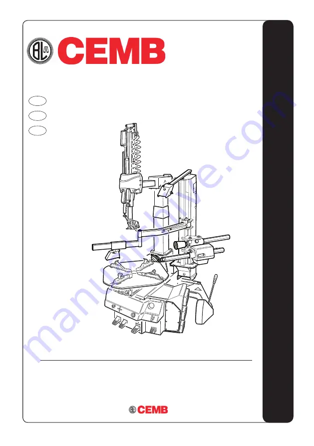
SM675TI  

User’s manual
Manuel d’utilisation
Manual de uso

EN

FR

ES

Summary of Contents for SM675TI

Page 1: ...41 706369 Fax 39 0341 700725 www cemb com garage cemb com Cemb Spa declines all liability for any damage to people or property caused by incorrect use of this product Subject to change without prior n...

Page 2: ...uction Manual should be considered an integral part of your equipment and should remain with the equipment However nothing in this manual and none of the devices installed on the equipment can replace...

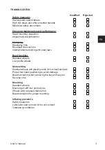
Page 3: ...nternal external locking with steel jaws Bead breaking Standard wheels Low profile wheels Demounting Standard wheels with plastic guards for tool head and lever Proper tool head positioning to avoid d...

Page 4: ...__________________ ___________________________________________________ ___________________________________________________ ___________________________________________________ _________________________...

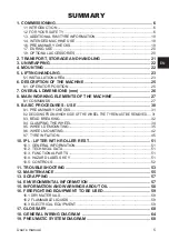
Page 5: ...RES USE 30 9 1 PRELIMINARY CHECKS 31 9 2 DECIDING FROM WHICH SIDE OF THE WHEEL THE TYRE MUST BE REMOVED 31 9 3 BEAD BREAKING 32 9 4 CLAMPING THE WHEEL 34 9 5 WHEEL DEMOUNTING 35 9 6 WHEEL mounting 42...

Page 6: ...dures and maintenance Italics are used to refer to specific parts of this manual that offer additional information or clarifications These references must be read in order to obtain information additi...

Page 7: ...nstructions it contains are not observed This manual makes continuous reference to the possibility that accidents can occur Any accident could lead to serious or fatal injuries to the operator or peop...

Page 8: ...rts away from moving parts Do not use tools other than those supplied with tyre changer Use lubricant that is specific for tyres in order to prevent tyre seizure Pay attention while handling the rim o...

Page 9: ...t PPE or equipment with equivalent certifications while ope rating the machine Consult your supervisor for additional instructions 18 Do not wear jewellery watches loose clothing ties and tie up long...

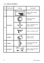
Page 10: ...XXXX ANNO DI COSTRUZIONE MANUFACTURED Mod V A kW Hz Ph bar psi LABEL MODEL SERIAL NUMBER 02 000102600 LABEL ROTATION TURNTABLE LABEL TURNTABLE OPE NING CLOSING LABEL COLUMN TILTING 4 600332 LABEL LIFT...

Page 11: ...ularly as outlined in the instruction manual F Remove all air from tire before loosening beads Remove valve core G Remove all wheel weights from rim before mounting or demounting to prevent damage H A...

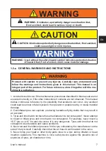
Page 12: ...0992 CAUTION RISK OF ELECTRIC SHOCK DO NOT OPEN COVER WARNING TO REDUCE THE RISK OF ELECTRIC SHOCK DO NOT EXPOSE THIS TIRE CHANGER TO RAIN WATER OR WET LOCATIONS WARNING THIS TIRE CHANGER DOES NOT CON...

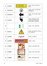
Page 13: ...t n 000103300 LABEL HAND CRUSHING HA ZARD BEAD BREAKER part n 000103400 LABEL LEG CRUSHING HAZARD BEAD BREAKER part n 000102900 LABEL RISK OF INJURY REAR POLE part n 000103100 LABEL DANGER TOOL HEAD L...

Page 14: ...rim carefully for defects Do not mount the tire if any defects are found G Seat beads and inflate the tire with short bursts of air while continuously checking the air pressure H Stand away from the t...

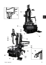
Page 15: ...User s manual 15 EN 01 05 02 18 03 04 21 08 06 07 10 11 20 22 12 14 15 16 16 17 19...

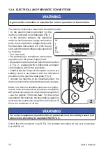
Page 16: ...30mA sensitivity install protection fuses on the power line that are suitably sized in accordance with the indications provided on the machine data plate Fig 1 connect the machine to an industrial so...

Page 17: ...ed below pedal A COMPLETELY LOW turntable closed pedal B COMPLETELY LOW pole not tilted A B 1 2 e TECHNICAL DATA Table top clamping capacity inside clamping 14 27 outside clamping 11 24 Rim width 405...

Page 18: ...tyre and rim dimensions Take care to avoid any damage to the tyre During inflation keep outside the vertical cylinder area occupied by the wheel The machine is equipped with an internal pressure limi...

Page 19: ...e safety procedures Information to be used for the training program includes as a minimum the information contained in this manual 2 Employers are required to make sure that every employee demonstrate...

Page 20: ...vibration is detected if a compo nent or system is not operating correctly or if you observe anything unusual immediately stop using the machine Identify the cause and implement all the necessary cor...

Page 21: ...t with package TI version 500 kg Ambient conditions for machine transport and storage Temperature 25 55 C WARNING Do not stack other goods on top of the packing to avoid damaging it Handling Tomovethe...

Page 22: ...allet make sure the items shown below have been removed Remove the upper part of the package and make sure that the machine has not suffered damage during transport identify the points for fastening t...

Page 23: ...machine in compliance with all the applicable safety standards in cluding but not limited to those issued by OSHA CAUTION IMPORTANT for the correct and safe operation of the equipment the ambient ligh...

Page 24: ...C 50 C WARNING Whenever the machine is disconnected from the pneumatic line for long periods before restoring the pneumatic supply check the configuration of the pedals as shown below DANGER Before p...

Page 25: ...in Volts A Input voltage in Amperes kW Absorbed power in kW Hz Frequency in Hz Ph Number of phases bar psi Operating pressure in bar and or psi Serial No machine serial number ISO 9001 company Quality...

Page 26: ...26 User s manual 7 OVERALL DIMENSIONS mm Packing dimensions vedi fig 10 Length 1500 T I min 1880 max Width 1120 min 1660 max Height 1850 min 2140 max B A H 10...

Page 27: ...es humidity of and lubricates the compressed air supplied 9 Bead breaker arm 10 Bead breaker 11 Wheel support 17 Wheel lift optional 18 Tyre inflation pedal 19 Pressure gauge 24 Working arm cylinder P...

Page 28: ...ng Posizione 0 stabile discesa ruota 8 1 b HORIZONTAL ARM 22 Locking button A working arm ascent B working arm descent C locked 23 Head control lever 8 1 c BEAD PRESSER 26 TPH upward downward control...

Page 29: ...the technical characteristics warnings mainte nance and any other information about the air tank optional consulttherelevantoperator sandmaintenancemanualprovided with the documentation of the accesso...

Page 30: ...risk of impact with parts of the body B A C P P WARNING AVOID ANY PHYSICAL DAMAGE Before carrying out maintenance on the machine 1 Put the machine in a stable con figuration with the horizontal axis c...

Page 31: ...alloy rims have a minimum A rim channel or do not have any channel Fig 13A These rims are not approved by DOT standards Department of Transportation The DOT initials certify that tyres comply with th...

Page 32: ...ose the turntable locking wedges towards the centre A Fig 14 keeping your hands away from moving parts 14b 14a A Press pedal A and bring it into completely lowered con figuration In this configuration...

Page 33: ...l It may be necessary to break the bead at several points to free it completely Release the pedal to reverse the motion of the bead breaking shoe After detaching the beads remove the old balancing wei...

Page 34: ...the arms into the non working position Press pedal to take the column into the non working position Turntablejawsopeningandclosingiscarried outbysequentiallypressingthecontrolpedal Fig 18 With the ja...

Page 35: ...ace the wheel on the turntable position the rim clamp arm in the working position Fig 20a activate valve so as to press the wheel on the turntable then clamp the wheel with the special pedal N B This...

Page 36: ...on The distance between rim and tool head will remain unchanged till the control button is in locking posi tion The operator can tilt the vertical post i e when handling a set of tyres having same dim...

Page 37: ...er bead demounting Check that the tool is correctly coupled with the tyre bead Operate the control valve to get the machine ready for the subsequent de mounting operation performed with the wheel at a...

Page 38: ...erate pedal 14 until the bead is com pletely demounted Fig 28 28 9 5 d Lower bead demounting Using tool carrying head Acting on the pedal rotate the turntable till a clamp would be exactly in front of...

Page 39: ...ed on the TPH console the bead lifter arm will move forward allowing the tool touching the lower rim edge The bead lifter arm will keep a safety distance of 2 3 mm from the rim edge Acting on the cont...

Page 40: ...r less head Quick system Acting on the pedal rotate the turntable till a clamp would be exactly in front of the operator and the yellow flag assembled on the turntable in correspondence of the TPH dis...

Page 41: ...l the tyre is completely demounted D Fig 30 9 5 f Demounting complete At the end of the demounting phase act on the commutator switch placed on the TPH console 17 Fig 9 in order to obtain the withdraw...

Page 42: ...es or death Also check that the rims are not deformed that their fastening holes have not become oval that they are not encrusted or rusted and that they have no sharp burrs on the valve holes Check t...

Page 43: ...that the tyre does not slip underneath the tool 9 6 e Bead presser roller positioning Lower the bead presser roller control A until it is level with the well of the rim 2 1 33a 33b 9 6 f Upper bead m...

Page 44: ...m groove and thus avoiding any effort or danger to the ope rator and for the rim 34a 34b WARNING Proceed with care in this stage to avoid applying excessive stress to the tyre It is recommended to sli...

Page 45: ...position the bead pressing tool at 3 o clock to press the bead into the rim grove Restart the rotation to complete the mounting phase Remove clamp bead pressing tool lever less head and bead presser r...

Page 46: ...producing hazardous flying debris that may result in an accident 2 Tyres and rims that do not have the same diameter are mismatched Never attempt to mount or inflate any tyre and rim that are mismatch...

Page 47: ...The tyre changer is not a safety device and does not prevent tyres and rims from exploding Keep all persons not working on the machine out of the working area 9 7 b TYRE INFLATION Make sure the wheel...

Page 48: ...e relevant section lubricate and turn the tyre on the rim Repeat the mounting operation described previously and check again 37 38 39 WARNING Risk of explosion During the bead insertion phase do not e...

Page 49: ...ards the operator Make sure that the wheel is clamped to the turntable from the inner side fig 40 Lower the vertical arm until it touches the rim fig 36 then clamp the arm in this position Remove the...

Page 50: ...NING RISK OF EXPLOSION Do not mount a tyre and a rim that do not have the same diameter e g 16 and 1 2 inch tyre and a 16 inch rim If the tyre is excessively inflated the air can be released by pressi...

Page 51: ...proper unreasonable and therefore not permissible In particular NEVER use the IPL to lift persons Before any operation on or with this device the contents of this instructions Manual must be read care...

Page 52: ...platform fig 46 2 Press the pedal fig 45 to raise the platform Hold the wheel with one hand as the platform moves so that the wheel is always balanced 3 Place the wheel on the turntable using the plas...

Page 53: ...the plug The motor is not running Check the microswitches of the pedal unit only for motor inverter Check the motor rotation control of the pedal unit Replace the inverter board only for motor inverte...

Page 54: ...rises too far from rim lamping plate not adjusted Adjust the plate Column does not tilt Column tilting cylinder faulty Replace column opening cylinder No air supply to cylinder Hoses folded Replace va...

Page 55: ...G Before carrying out any regular maintenance operation or topping up with lubricant disconnect the machine from the compressed air supply line WARNING The manufacturer declines all responsibility for...

Page 56: ...20 oil equal to 50cc The filter regulator FR has an automatic condensation drain system therefore in condi tions of normal use special maintenance is not required The condensate may however be drained...

Page 57: ...below only applies to equipment with the barred bin symbol on the rating plate This product may contain substances that are potentially harmful to the environment and human health unless disposed of...

Page 58: ...to dispose of old products and im prove quality of life by preventing the discharge of potentially hazardous substances into the environment 15 INFORMATION AND WARNINGS ABOUT OIL Disposal of waste oil...

Page 59: ...ately Eyes rinse with plenty of running water and seek medical attention immediately Skin wash with soap and water 16 FIREFIGHTING EQUIPMENT TO BE USED Refer to the table below to choose the most suit...

Page 60: ...ions 2 Edge or bracing It is an insert of metallic or textile fabric placed at the outer part of the bead it is used to protect the carcass plies from sliding against the rim 3 Casing This is the resi...

Page 61: ...wall which is more exposed to accidental rubbing 8 Sidewall This is the area between the shoulder and the centring band It consists of a more or less thin layer of rubber which protects the casing pli...

Page 62: ...he section in contact with the tyre It is made with dif ferent geometric shapes that serve to ensure easy assembly of the tyre inserting the bead into the channel safety on the move in terms of anchor...

Page 63: ...ng tool A tool intended for use when mounting the top bead It is positioned so that it engages the shoulder of the rim and maintains the upper tyre bead inside the well It is generally used for mounti...

Page 64: ...2 x 9 10 x 7 8 x 5 6 x 3 4 x 1 2 L 0 R 1 2 3 L1 ELEMENTI Elements CONTATTI Contacts W2 U1 U2 V2 V1 W1 W2 U1 U2 V2 V1 W1 200 220 240V 380 415 440V MORSETTIERA Junction Box F F F Power Phase 400V 3 50 H...

Page 65: ...1 12 x 9 10 x 7 8 x 5 6 x 3 4 x 1 2 L 0 R 1 2 3 ELEMENTI Elements CONTATTI Contacts F F Power Phase Neutral 230V 1 50 Hz 250V 16A 250V 16A 240V 1 50 Hz 250V 16A 250V 16A 220V 1 60 Hz 250V 16A 250V 16A...

Page 66: ...3 5 7 9 11 2 4 6 8 10 12 13 15 17 19 21 23 14 16 18 20 22 24 L2 23 24 x x x 21 22 x 19 20 x 17 18 x x 15 16 x x 13 14 x 11 12 x 9 10 x 7 8 x x 5 6 x x 3 4 x 1 2 L2 L1 0 R 1 2 3 4 5 6 V2 U2 W2 W1 V1 U1...

Page 67: ...ANGER MOTOINVERTER VERSION AP1 N PE L1 F F XS1 L1 N SQ3 XB1 SQ1 SQ2 M1 R T S 1 2 3 4 U V W BROWN BLACK BLUE GRUPPO MOTORE MOTOR UNIT GRUPPO COMANDI CONTROL SWITCH Power Phase Neutral 200 230V 1 50 60...

Page 68: ...68 User s manual 19 PNEUMATIC SYSTEM DIAGRAM P max 12 bar 33 32 31 30 29 28 1 2 4 3 5 6 7 8 9 10 11 12 12 13 13 15 14 34 35 36 16 17 19 18 20 21 22 23 24 25 27 26 H G F E D N L M I A B C...

Page 69: ...Note...

Page 70: ...entmanueld utilisationdoit treconsid r commepartieint grantedel quipement et devra toujours l accompagner Toutefois aucun l ment contenu dans le pr sent manuel et aucun dispositif install sur l quipem...

Page 71: ...envers Blocage interne externe avec griffes en acier D talonnage Roues standard Roues surbaiss es D montage Roues standard avec protections en plastique pour t te op rante et levier Positionnement cor...

Page 72: ..._______________________ ___________________________________________________ ___________________________________________________ ___________________________________________________ ____________________...

Page 73: ...S 99 9 2 TABLIR DE QUEL C T DE LA ROUE D MONTER LE PNEU 99 9 3 DETALLONAGE 100 9 4 BLOCAGE ROUE 102 9 5 d montage DE LA ROUE 103 9 6 montage DE LA ROUE 110 9 7 Le GONFLAGE DES PNEUS 113 10 ELEVATEUR I...

Page 74: ...ures et l entretien L italique est utilis pour se r f rer des parties sp cifiques du pr sent manuel qui fournissent des informations compl mentaires ou des claircissements Ces r f rences doivent tre l...

Page 75: ...tien fournies dans le pr sent manuel ou l inobservation des autres instructions pourrait provoquer des accidents Ce manuel contientdesnotesfaisant continuellement allusion aux risques d accidents Tout...

Page 76: ...de d montage et de montage Tenir les mains et les doigts l cart de la t te durant le fonctionnement Tenir les mains et les autres parties du corps l cart des organes et pi ces en mouvement Ne pas uti...

Page 77: ...nner la machine en toute s curit 17 Toujours porter les quipements de protection individuelle EPI ho mologu s et autoris s OSHA CE ou avec des certifications quivalentes durant le fonctionnement de la...

Page 78: ...MANUFACTURED Mod V A kW Hz Ph bar psi AUTOCOLLANT NUM RO DE S RIE MOD LE 02 000102600 AUTOCOLLANT ROTATION AUTOCENTREUR AUTOCOLLANT OUVERTU REFERMETURE AUTOCEN TREUR AUTOCOLLANT BASCULEMENT COLONNE 4...

Page 79: ...clothing away from moving parts E Service machine regularly as outlined in the instruction manual F Remove all air from tire before loosening beads Remove valve core G Remove all wheel weights from ri...

Page 80: ...RISqUES 21 4 600992 CAUTION RISK OF ELECTRIC SHOCK DO NOT OPEN COVER WARNING TO REDUCE THE RISK OF ELECTRIC SHOCK DO NOT EXPOSE THIS TIRE CHANGER TO RAIN WATER OR WET LOCATIONS WARNING THIS TIRE CHANG...

Page 81: ...LANT DANGER D CRASEMENT DES MAINS D TALONNEUR parte n 000103400 AUTOCOLLANT DANGER D CRASEMENT DES JAMBES D TALONNEUR parte n 000102900 AUTOCOLLANT DANGER DE COLLISION DU POTEAU ARRI RE parte n 000103...

Page 82: ...refully for defects Do not mount the tire if any defects are found G Seat beads and inflate the tire with short bursts of air while continuously checking the air pressure H Stand away from the tire an...

Page 83: ...Manuel d utilisation 83 FR 01 05 02 18 03 04 21 08 06 07 10 11 20 22 12 14 15 16 16 17 19...

Page 84: ...e la ligne d alimentation ayant un amp rage conforme aux indications sp cifi es sur la plaque des donn es de la machine Fig 1 brancher la machine une prise de type industriel le raccordementauxprisesd...

Page 85: ...figuration ci dessous indiqu e p dale A TOUT EN BAS autocentreur ferm p dale B TOUT EN BAS p le pas renvers A B 1 2 e DONN ES TECHNIQUES Plage des dimensions de la roue interne 14 27 externe 11 24 Lar...

Page 86: ...s de la jante soient compatibles Faire attention aux risques de l sions du pneu Pendant le gonflage tenir une position en dehors du volume cylindrique vertical occup par la roue La machine est dot e d...

Page 87: ...p cifique du type de roue sur lequel ils interviennent et aux consignes de s curit Les informations utiliser dans le programme de formation incluent au minimum les informations contenues dans le pr se...

Page 88: ...ication etc 1 7 PENDANT L UTILISATION Si l on per oit des bruits tranges ou des vibrations insolites ou bien si un composant ou un syst me ne fonctionne pas bien ou encore si l on constate une conditi...

Page 89: ...llage Version TI 500 kg Conditions du milieu de transport et stockage de la machine Temp rature 25 55 C ATTENTION Pour viter tout endommagement ne pas superposer d autres colis sur l emballage Manuten...

Page 90: ...irer la machine de la palette s assurer que les l ments suivants ont t retir s de la palette Lib rer la machine de la partie sup rieure de l emballage s assurer qu elle n a pas t endommag e pendant le...

Page 91: ...ati re de s curit en vigueur y compris mais pas seulement celles pr vues par OSHA Agence europ enne pour la s curit et la sant au travail AVERTISSEMENT IMPORTANT pour une utilisation correcte et s re...

Page 92: ...e fois que la machine est d connect e du circuit pneumatique pendant de longues p riodes avant de r tablir l alimentation pneumatique v rifier la configuration des p dales de commande comme indiqu ci...

Page 93: ...ourant absorb en Amp res kW Puissance absorb e en kW Hz Fr quence en Hz Ph Nombre de phases bar psi Pressiondeserviceenbarset ouenpsi Serial N le num ro de s rie de la machine ISO 9001 Certification d...

Page 94: ...94 Manuel d utilisation 7 DIMENSIONS D ENCOMBREMENT mm Dimensions d encombrement vedi fig 10 Longueur 1500 T I min 1880 max Largeur 1120 min 1660 max Hauteur 1850 min 2140 max B A H 10...

Page 95: ...ubrifier l air d alimentation 9 Bras d talonneur 10 Palette du d talonneur 11 Appui roue 17 l vateur de roue optional 18 P dale pour gonfle tubeless 19 Manom tre 24 V rin de descente de la tourelle mo...

Page 96: ...ORIZONTAL 22 Commande de mont e descente du bras vertical A Mont e B Descente C Ver rouillage 23 Commande de la tourelle mobile de montage d montage 8 1 c POUSSE TALON 26 Valve de commande mont e desc...

Page 97: ...istiques techniques les avertissements l entretien l entretien et toute autre information relative au r servoir d air en option le manuel d utilisation et d entretien fourni avec la documentation des...

Page 98: ...er un danger potentiel de collision avec des parties du corps B A C P P ATTENTION VITER LES DOMMAGES PHYSIQUES Avantd effectuerdestravauxd entretien sur la machine 1 Placer la machine dans une con fig...

Page 99: ...ou pas de creux du tout Fig 13A Ces jantes ne sont pas approuv es par les normes du DOT Department of Transportation D partement des Transports L acronyme DOT certifie la conformit des pneus aux norm...

Page 100: ...e centre A Fig 16 en gardant les mains loin des pi ces en mouvement 14b 14a A Appuyer sur la p daleAet l amener la configuration compl tement abaiss e Dans cette configuration les griffes sont compl t...

Page 101: ...eut tre n cessaire de d talonner de diff rents endroits pour lib rer compl tement le talon En rel chant la p dale on inverse la direction de la palette de d talonnage Une fois les talons d tach s enle...

Page 102: ...loquer les bras en position hors service Appuyersurlap dale pourmettre la colonne en position hors service L ouverture et la fermeture des griffes de l autocentreursefaitenappuyantsuccessivement surla...

Page 103: ...mani re suivante Pr s lectionnez l overture de l auto centrant de mani re ce que les mors sont en contact du pneumatique et le plus pr possible du bord de la jante amenez le bras dans la position de t...

Page 104: ...etravail Fig 21a Presser le bloc 1 Fig 21a pour fixer la position de l outil La distance entre la jante et l outil reste constante jusqu quandleboutondecommandeestactionn en position de blocage L oper...

Page 105: ...rtantdefairetournerl g rement le mandrin 24 1 2 1 25 9 5 c D montage du talon sup rieur V rifier que l outil ait accroch le talon du pneu Actionnerlacommande poursepr parer l op rationsuivanteded mont...

Page 106: ...montage complet du talon Fig 28 28 9 5 d D montage du talon inf rieur avec l utilisation de la tourelle porte outil Appuyer sur la p dale de l autocentreur de sorte qu une des griffes soit tourn e ver...

Page 107: ...s le centre de l autocentreur de fa on porter le palpeur en contact avec le bord inf rieur de la jante Le bras l ve talon s carte automatiquement de la jante de 2 3mm Exercer une pouss e avec le disqu...

Page 108: ...a tourelle porte outil Appuyer sur la p dale de l autocentreur de sorte qu une des griffes soit tourn e vers l op rateur et que la fl che jaune situ e sur l autocentreur soit tourn e en direction du d...

Page 109: ...tan ment lever par coups commande le disque Tourner jusqu au d montage complet du pneu D Fig 30 9 5 f D montage compl t Une fois le d montage compl t reporter le bras souleve talon en position hors tr...

Page 110: ...nt que les jantes ne sont pas d form es que leurs trous de fixation ne sont pas devenus ovales qu elles ne sont pas incrust es ou rouill es et qu elles n ont pas de bavures pointues sur les trous des...

Page 111: ...tion que le pneu ne glisse pas sous l outil 9 6 e Positionnement du disque d talonneur Rapprocher le groupe d talonneur 2 3mm Fig 33a Baisser le disque d talonneur commande jusqu au niveau du creux de...

Page 112: ...ntreur tourne le presse talon tourne en m me temps que le pneu et le maintient dans le creux on peut alors introduire le deuxi me talon sans effort et sans risque pour l op rateur et sans risque d ab...

Page 113: ...exer ant une pression trois heures Reprendre la rotation jusqu au montage complet du pneu Retirer l tau le presse talon l outil et le rouleau presse talon Amener le groupe presse talon et le rouleau...

Page 114: ...ous 1 Des pneus trop gonfl s peuvent clater et provoquer la dispersion de d tritus susceptibles de causer des accidents 2 Des pneus et des jantes qui n ont pas le m me diam tre sont incompatibles et d...

Page 115: ...r la pression prescrite par le fabricant du pneu Le d monte pneus n est pas un dispositif de s curit et ne peut donc pas em p cher l clatement de pneus et de jantes Veiller ce que les personnes resten...

Page 116: ...la proc dure d crite dans la section relative lubrifier et faire tourner le pneu sur la jante R p ter l op ration de montage d crite pr c demment en effectuant un autre contr le 37 38 39 ATTENTION Da...

Page 117: ...assurer que la roue est bloqu e sur l autocentreur de l int rieur fig 40 Baisser le bras vertical jusqu au contact avec la jante fig 36 ensuite bloquer le bras dans cette position Retirer le noyau de...

Page 118: ...DANGER D EXPLOSION Ne pas monter un pneu sur une jante de diam tre diff rent exemple pneu de 16 5 sur jante de 16 Si le pneu est trop gonfl il est possible d vacuer l air en appuyant sur le bouton man...

Page 119: ...inappropri e d nu e de sens et donc non auto ris e Par exemple il est interdit d utiliser l ipl pour soulever les personnes Avant de commencer une quelconque op ration il est indispensable de lire et...

Page 120: ...verticale sur la plate forme fig 46 2 Appuyer sur la p dale A fig 45 pour que la plate forme se rel ve tout en accompagnant et en maintenant la roue en quilibre de la main durant la course enti re 3...

Page 121: ...ble dans la fiche Le moteur ne tourne pas Contr ler les microrupteurs du p dalier uniquement pour inverseurs Contr ler la commande de rotation moteur du p dalier Remplacer la carte de l inverseur uniq...

Page 122: ...gler la plaque La potence ne s ouvre pas V rin d ouverture de la potence d fectueux Remplacer le v rin d ouverture de la potence L air n arrive pas au v rin Tuyaux pli s Remplacer la soupape V rifier...

Page 123: ...us pression ATTENTION Avant de proc der un entretien de routine ou une lubrification compl men taire d connecter la machine de la ligne d alimentation pneumatique ATTENTION Le constructeur d cline tou...

Page 124: ...d vacuationducondensat de l eau de sorte que dans des conditions normales d utilisation il ne n cessite pas d entretien particulier il est toutefois possible tout moment de pr voir une vacuation manue...

Page 125: ...ALES La proc dure suivante d limination doit tre appliqu e exclusivement aux machines dont la plaque des donn es reporte le symbole de la poubelle barr e Cet appareil peut contenir des substances noci...

Page 126: ...sources naturelles utilis esdanslafabricationdesappareils lectriqueset lectroniques d optimiserl exploitation desd chetteriesetd am liorerlaqualit delavie en vitantquedessubstancespotentiellement dang...

Page 127: ...et se contacter d s que possible le poste m dical Peau laver l eau et savon 16 MOYENS UTILISER POUR LUTTER CONTRE LES INCENDIES Pour choisir l extincteur le plus appropri consulter le tableau suivant...

Page 128: ...onne adh rence dans des conditions s ches et humides ainsi que des conditions de fonctionnement silencieux 2 Bord ou renfort Il s agit d un insert en m tal ou en tissu textile plac la partie ext rieur...

Page 129: ...trage Il s agit d une petite marque indiquant la circonf rence de la partie sup rieure du talon et servant de r f rence pour v rifier le centrage correct du pneu sur la jante apr s montage 7 Cordon de...

Page 130: ...ieur est recouvert d une fine couche de caoutchouc sp cial imperm able l eau appel rev tement Ceci permet d assurer l tanch it de l air sous pression contenu dans la carcasse Ce type de pneu doit tre...

Page 131: ...e Syst medegonflagedestubeless Syst medegonflage qui facilite le gonflage des pneus tubeless Entalonnage Cette op ration est obtenue pendant la phase de gonflage et garantit un centrage parfait entre...

Page 132: ...11 12 x 9 10 x 7 8 x 5 6 x 3 4 x 1 2 L 0 R 1 2 3 L1 ELEMENTI Elements CONTATTI Contacts W2 U1 U2 V2 V1 W1 W2 U1 U2 V2 V1 W1 200 220 240V 380 415 440V MORSETTIERA Junction Box F F F Power Phase 400V 3...

Page 133: ...x 11 12 x 9 10 x 7 8 x 5 6 x 3 4 x 1 2 L 0 R 1 2 3 ELEMENTI Elements CONTATTI Contacts F F Power Phase Neutral 230V 1 50 Hz 250V 16A 250V 16A 240V 1 50 Hz 250V 16A 250V 16A 220V 1 60 Hz 250V 16A 250V...

Page 134: ...s 1 3 5 7 9 11 2 4 6 8 10 12 13 15 17 19 21 23 14 16 18 20 22 24 L2 23 24 x x x 21 22 x 19 20 x 17 18 x x 15 16 x x 13 14 x 11 12 x 9 10 x 7 8 x x 5 6 x x 3 4 x 1 2 L2 L1 0 R 1 2 3 4 5 6 V2 U2 W2 W1 V...

Page 135: ...E CHANGER MOTOINVERTER VERSION AP1 N PE L1 F F XS1 L1 N SQ3 XB1 SQ1 SQ2 M1 R T S 1 2 3 4 U V W BROWN BLACK BLUE GRUPPO MOTORE MOTOR UNIT GRUPPO COMANDI CONTROL SWITCH Power Phase Neutral 200 230V 1 50...

Page 136: ...136 Manuel d utilisation 19 SCH MA CIRCUIT PNEUMATIQUE P max 12 bar 33 32 31 30 29 28 1 2 4 3 5 6 7 8 9 10 11 12 12 13 13 15 14 34 35 36 16 17 19 18 20 21 22 23 24 25 27 26 H G F E D N L M I A B C...

Page 137: ...Note...

Page 138: ...ente Manual de instrucciones debe ser considerado parte integrante del equipo e incluido en el mismo Sin embargo nada de lo que contiene el presente manual ni ning n dispositivo instalado en el equipo...

Page 139: ...tas de canal invertido Bloqueo interno externo con garras de acero Destalonado Ruedas est ndar Ruedas bajas Desmontaje Ruedas est ndar con protecciones de pl stico para torreta y palanca Posicionamien...

Page 140: ..._____________________ ___________________________________________________ ___________________________________________________ ___________________________________________________ ______________________...

Page 141: ...RELIMINARES 167 9 2 ESTABLECER DE QU LADO DE LA RUEDA DESMONTAR EL NEUM TICO 167 9 3 DESTALONADO 168 9 4 BLOCCAGGIO RUOTA 170 9 5 desmontaje DE LA RUEDA 171 9 6 MONTAJE DE LA RUEDA 178 9 7 EL INFLADO...

Page 142: ...tenance Italics are used to refer to specific parts of this manual that offer additional information or clarifications These references must be read in order to obtain information additional to the in...

Page 143: ...trucciones contenidas en el mismo podr an producirse accidentes En el presente manual se se ala continuamen te la posibilidad de que se produzcan accidentes Cualquier accidente podr a causar lesiones...

Page 144: ...sonas que circulan por el lugar lejos de la desmontadora de neum ticos Mantener las manos y los dedos lejos del borde de la llanta durante el proceso de desmontaje y montaje Mantenerlasmanosylosdedosl...

Page 145: ...pacidades para hacer funcionar la m quina de manera segura 17 Usarsiempreequiposdeprotecci nindividual EPI aprobadosyautoriza dosporOSHA CEoconcertificacionesequivalentesduranteelfuncionamiento de la...

Page 146: ...DI COSTRUZIONE MANUFACTURED Mod V A kW Hz Ph bar psi ADHESIVO MATR CULA MODELO 02 000102600 ADHESIVO ROTACI N AUTOCENTRANTE ADHESIVO APERTURA CIERRE AUTOCENTRANTE ADHESIVO VUELCO CO LUMNA 4 600332 AD...

Page 147: ...from moving parts E Service machine regularly as outlined in the instruction manual F Remove all air from tire before loosening beads Remove valve core G Remove all wheel weights from rim before moun...

Page 148: ...4 600992 CAUTION RISK OF ELECTRIC SHOCK DO NOT OPEN COVER WARNING TO REDUCE THE RISK OF ELECTRIC SHOCK DO NOT EXPOSE THIS TIRE CHANGER TO RAIN WATER OR WET LOCATIONS WARNING THIS TIRE CHANGER DOES NO...

Page 149: ...PELIGRO DE APLASTAMIENTO MANOS DE STALONADOR part n 000103400 ADHESIVO PELIGRO DE APLASTAMIENTO PIERNAS DE STALONADOR part n 000102900 ADHESIVO PELIGRO DE CHO QUE COLUMNA TRASERA part n 000103100 ADH...

Page 150: ...Inspect the tire and rim carefully for defects Do not mount the tire if any defects are found G Seat beads and inflate the tire with short bursts of air while continuously checking the air pressure H...

Page 151: ...Manual de uso 151 ES 01 05 02 18 03 04 21 08 06 07 10 11 20 22 12 14 15 16 16 17 19...

Page 152: ...A montar fusibles de protecci n en la l nea de alimentaci n de dimensiones conformes a las in dicaciones detalladas en la relativa placa de datos de la m quina Fig 1 conectar la m quina a una toma ind...

Page 153: ...dal A TODO ABAJO autocentrante cerrado pedal A TODO ABAJO polo no volcado A B 1 2 e DATOS T CNICOS Capacidad de bloqueo del autocentrante Desde el interior 14 27 Desde el exterior 11 24 Anchura de la...

Page 154: ...a Prestaratenci naeventualeslesionesdelneum tico Durante el inflado posicionarse fuera del volumen cil ndrico vertical ocupado por la rueda La m quina est dotada de una v lvula limitadora de presi n i...

Page 155: ...s no intervengan en las ruedas a menos que los mismos hayan efectuado la adecuada formaci n relativa a los procedimientos correctos de mantenimiento del tipo de rueda sobre la que est n trabajando y a...

Page 156: ...nte estos controles preliminares No usar la m quina si est fuera de servicio por puesta a punto mantenimiento lubricaci n etc 1 7 DURANTE EL USO En caso de percibir ruidos extra os o vibraciones inusu...

Page 157: ...Versi n TI 500 kg Condiciones del ambiente de transporte y almacenamiento de la m quina Temperatura 25 55 C ATENCI N Para evitar da os no superponer otros objetos sobre el embalaje Desplazamiento Par...

Page 158: ...na del pallet asegurarse de que se hayan retirado del mismo los siguientes elementos indicados a continuaci n Liberarlam quinadelapartesuperior delembalaje asegurarsedequenose haya da ado durante el t...

Page 159: ...a m quina en conformidad con todas las normas sobre la seguridad aplicables incluidas pero no limitadas a estas las emitidas por OSHA ADVERTENCIA IMPORTANTE para un uso correcto y seguro del equipo re...

Page 160: ...N Siempre que la m quina est desconectada de la l nea neum tica durante largos per odos de tiempo antes de restablecer la alimentaci n neum tica comprobar la configuraci n de los pedales de control co...

Page 161: ...bida en kW Hz Frecuencia en Hz Ph N mero de las fases bar psi Presi n de funcionamiento en bar y o psi Serial N El n mero de matr cula de la m quina ISO 9001 Certificaci n del Sistema de Calidad de la...

Page 162: ...162 Manual de uso 7 DIMENSIONES mm Dimensiones embalaje vedi fig 10 Anchura 1500 T I min 1880 max Profundidad 1120 min 1660 max Altura 1850 min 2140 max B A H 10...

Page 163: ...9 Brazo destalonador 10 Pala destalonadora 11 Soporte destalonador 17 Elevador de rueda opcional 18 Pedal para hincha tubeless 19 Man metro 24 Cilindro de bajada torreta m vil 25 Cilindro de mando he...

Page 164: ...Posici n 0 estable bajada de la rueda 8 1 b BRAZO HORIZONTAL 22 Pulsador subida bajada brazo vertical A subida B bajad a C bloqueado 23 Palanca de mando torreta 8 1 c PRENSA TAL N 26 V lvula de mando...

Page 165: ...aracter sticas t cnicas advertencias mantenimien to y cualquier otra informaci n relativa al dep sito del aire opcional el manual de uso y mantenimiento suministrado con la documentaci n del accesorio...

Page 166: ...encial de colisi n con partes del cuerpo B A C P P ATENCI N EVITAR DA OS F SICOS Antes de realizar intervenciones de mantenimiento en la m quina 1 Colocar la m quina en una confi guraci n estable con...

Page 167: ...ienen canal alguno Fig 13A Estas llantas no est naprobadasporlasnormasdelDOT Department of Transportation Departamento de Transportes El acr nimo DOT certifica la conformidad de los neum ticos con las...

Page 168: ...niendo las manos alejadas de las partes en movimiento 14b 14a A Pulsar el pedal A y llevarlo a la configuraci n comple tamente abajo En esta configuraci n las garras est n completamente cerradas Fig 1...

Page 169: ...l se invierte el moto de la paleta destalonadora Una vez liberados los talones retirar los an tiguos pesos de equilibrado Lubricar el neum tico con cuidado a lo largo de toda la circunferencia del tal...

Page 170: ...ici n sin trabajo Pisarelpedal parallevarlacolumna a la posici n sin trabajo La apertura y el cierre de las garras del auto centrante serealizanpisandosecuencialmente el pedal de mando Fig 18 Con las...

Page 171: ...n una medida levemente superior a la medida de la rueda apoyar la rueda en el plato autocentrante colocar el brazo prensa llanta en posici n de trabajo Fig 20a accionar la v lvula para presionar la ru...

Page 172: ...de la llanta fig 22a ATENCI N Lograr la correcta posici n ayud n dose con el pu o 2 Fig 21a Presionar el mando de bloqueo 1 Fig 21a para fijar la posici n de la herramienta La distancia entre la llant...

Page 173: ...a rotaci n del autocentrante 24 1 2 1 25 9 5 c Desmontaje del tal n superiore Verificar que la herramienta haya enganchado el tal n del neum tico Accionarelmando paraprepararseparalaposterioroperaci n...

Page 174: ...raciones accionar el pedal hasta lograr el desmontaje completo del tal n Fig 28 28 9 5 d Desmontaje del tal n inferior utilizando la torreta portaherramienta Pisar el pedal del autocentrante hasta que...

Page 175: ...l TPH el brazo alza tal n se deslizar hacia el centro del autocentrante hasta colocar el palpador en contacto con el borde inferior de la llanta Autom ticamente el brazo alza tal n se separar de la ll...

Page 176: ...edal para colocar la columna vertical en posici n de reposo Pisar el pedal del autocentrante hasta que una garra se oriente hacia el operador y la flecha amarilla situada en el autocentrante se encuen...

Page 177: ...el completo de smontaje del neum tico D Fig 30 A B C D 30 9 5 f Desmontaje concluido Una vez concluido el desmontaje accionar el conmutador situado en la consola de mando del TPH para hacer retroceder...

Page 178: ...Comprobar tambi n que las llantas no est n deformadas que sus orificios de fijaci n no est n ovalados que no est n incrustados ni oxidados y que no tengan rebabas afiladas en los orificios de la v lv...

Page 179: ...um tico no deslice bajo la herramienta 9 6 e Posicionamiento del rodillo prensa tal n Acercar el rodillo prensa tal n al borde de la llanta 2 3mm y bloquear su posici n enroscando el pomo Fig 33a Baja...

Page 180: ...neum tico consiguiendo de mantener el segundo tal n dentro del canal sin esfuerzo o riesgos para el operador 34a 34b ATENCI N Cuando el dispositivo prensa tal n llega en posici n de 6 horas reducir l...

Page 181: ...l canal ejerciendo una presi n en la posici n de las 3 horas Reiniciar la rotaci n hasta montar completamente el neum tico Quitar la mordaza el prensa tal n la herramienta y el rodillo prensa tal n Ll...

Page 182: ...mente inflados pueden explotar causando la dispersi n en el aire de detritos que pueden provocar accidentes 2 Los neum ticos y llantas que no tienen el mismo di metro se consideran no corres pondiente...

Page 183: ...n recomendada por el fabricante del neum tico Ladesmontadoradeneum ticosnoesundispositivodeseguridadynoevitar la explosi ndeneum ticosyllantas Manteneradistanciaalaspersonaspresentes 9 7 b INFLADO DE...

Page 184: ...ecci n correspondiente lubricar y girar el neum tico sobre la llanta Repetir la operaci n de montaje anteriormente ilustrada y efectuar una ulterior verificaci n 37 38 39 ATENCI N Peligro de explosi n...

Page 185: ...te desde la parte interna fig 40 Introducir el cono de centrado en el brazo prensa llanta colocarelbrazoenposici ndetrabajo accionar el mando 16 hasta que el cono entre en contacto con la llanta fig 3...

Page 186: ...que no pre senten el mismo di metro por ejemplo neum tico de 16 pulgadas y 1 2 con una llanta de 16 pulgadas En el caso en que el neum tico est inflado excesivamente es posible purgar el aire presion...

Page 187: ...adura Cualquier otro uso se debe considerar impropio y por tanto irracional y no permitido En particular nunca utilice el ipl para levantar personas Antes de comenzar cualquier tipo de operaci n es in...

Page 188: ...rtical en la plataforma fig 46 2 Pise el pedal A fig 45 para obtener la elevaci n de la plataforma acom pa andoymanteniendolaruedaenequilibrioconunamanoalolargodetodoelrecorrido 3 Coloque la rueda en...

Page 189: ...r las conexiones del cable en el enchufe El motor no gira Controlar los microinterruptores de los pedales solo para motor inversor Controlar el mando rotaci n motor de los pedales Sustituir la tarjeta...

Page 190: ...ado de la llanta Placa bloqueo no regulada Regular placa Columna no abre Cilindro de apertura columna averiado Sustituir el cilindro de apertura columna No llega aire al cilindro Tubos doblados Sustit...

Page 191: ...o de mantenimiento o ordinario o rellenado de lubricante desconectar la m quina de la l nea de alimentaci n neum tica ATENCI N El fabricante declina cualquier responsabilidad en caso de reclamaciones...

Page 192: ...del agua por lo que en condiciones normales de uso no requiere ning n tipo de mantenimiento particular de todos modos es posible realizar en cualquier momento un drenaje manual fig 47d Normalmente no...

Page 193: ...FORMACI N MEDIOAMBIENTAL Elsiguienteprocedimientodeeliminaci nsedebeaplicarexclusivamentealasm quinas donde la placa de datos de la misma presenta el s mbolo del contenedor tachado Este producto puede...

Page 194: ...todos se puede reducir la cantidad de recursos naturales empleados para la realizaci n de equipos el ctricos y electr nicos minimizar el uso de vertederos para la eliminaci n de los productos y mejor...

Page 195: ...al aire libre y luego al ambulatorio Ojos mojarabundantementeconaguaydirigirselom sr pidoposibleauncentrosanitario Piel lavar con agua y jab n 16 MEDIDAS DE PREVENCI N DE INCENDIOS UTILIZABLES Para e...

Page 196: ...la abrasi n y agarre en condiciones secas y h medas as como condiciones de funcionamiento silenciosas 2 Borde o refuerzo Se trata de un inserto de metal o tejido colocado en la parte exterior del tal...

Page 197: ...la parte superior del tal n y se utiliza como referencia para comprobar el correcto centradodelneum ticoenlallantadespu sdelmontaje 7 Bordillodeprotecci n Esunrelievecircunferencial situado en la zona...

Page 198: ...izado contenido en la carcasa Este tipo de neum tico debe montarse en llantas espec ficas directamente sobre las que est fijada la v lvula II Llanta Rueda La llanta es el elemento met lico r gido que...

Page 199: ...e neum ticos tubeless Entalonado Esta operaci n se obtiene durante la fase de inflado y garantiza un centrado perfecto entre el tal n y el borde de la llanta Pinza prensa tal n Esta herramienta est de...

Page 200: ...12 x 9 10 x 7 8 x 5 6 x 3 4 x 1 2 L 0 R 1 2 3 L1 ELEMENTI Elements CONTATTI Contacts W2 U1 U2 V2 V1 W1 W2 U1 U2 V2 V1 W1 200 220 240V 380 415 440V MORSETTIERA Junction Box F F F Power Phase 400V 3 50...

Page 201: ...11 12 x 9 10 x 7 8 x 5 6 x 3 4 x 1 2 L 0 R 1 2 3 ELEMENTI Elements CONTATTI Contacts F F Power Phase Neutral 230V 1 50 Hz 250V 16A 250V 16A 240V 1 50 Hz 250V 16A 250V 16A 220V 1 60 Hz 250V 16A 250V 16...

Page 202: ...3 5 7 9 11 2 4 6 8 10 12 13 15 17 19 21 23 14 16 18 20 22 24 L2 23 24 x x x 21 22 x 19 20 x 17 18 x x 15 16 x x 13 14 x 11 12 x 9 10 x 7 8 x x 5 6 x x 3 4 x 1 2 L2 L1 0 R 1 2 3 4 5 6 V2 U2 W2 W1 V1 U...

Page 203: ...ANGER MOTOINVERTER VERSION AP1 N PE L1 F F XS1 L1 N SQ3 XB1 SQ1 SQ2 M1 R T S 1 2 3 4 U V W BROWN BLACK BLUE GRUPPO MOTORE MOTOR UNIT GRUPPO COMANDI CONTROL SWITCH Power Phase Neutral 200 230V 1 50 60...

Page 204: ...204 Manual de uso 19 ESQUEMA INSTALACI N NEUM TICA P max 12 bar 33 32 31 30 29 28 1 2 4 3 5 6 7 8 9 10 11 12 12 13 13 15 14 34 35 36 16 17 19 18 20 21 22 23 24 25 27 26 H G F E D N L M I A B C...

Page 205: ...Note...

Page 206: ...Note...

Page 207: ......

Page 208: ...ORIGINAL INSTRUCTIONS TRADUCTION DE LA LANGUE D ORIGINE TRADUCCI N DEL IDIOMA ORIGINAL COMIM Cod 4 136545 11 2018...

Reviews: