


13
Negative
is the amount of compensation applied when you
release the button, winding the motors back in the other
direction to resume tracking .
Normally both values should be the same . You will need to
experiment with different values (from 0-99); a value between
20 and 50 is usually best for most visual observing, whereas a
higher value may be necessary for photographic guiding .
To set the anti-backlash value, scroll down to the
anti-backlash
option and press ENTER . While viewing an object in the
eyepiece, observe the responsiveness of each of the four arrow
buttons . Note which directions you see a pause in the star
movement after the button has been pressed . Working one axis
at a time, adjust the backlash settings high enough to cause
immediate movement without resulting in a pronounced jump
when pressing or releasing the button . Now, enter the same
values for both positive and negative directions . If you notice
a jump when releasing the button, but setting the values lower
results in a pause when pressing the button, go with the higher
value for positive, but use a lower value for negative . The
telescope will remember these values and use them each time
it is turned on until they are changed .
Filter Limits
— When an alignment is complete, the telescope
automatically knows which celestial objects are above the
horizon . As a result, when scrolling through the database
lists (or selecting the Tour function), the hand control will
display only those objects that are known to be above the
horizon when you are observing . You can customize the object
database by selecting altitude limits that are appropriate for
your location and situation . For example, if you are observing
from a mountainous location where the horizon is partially
obscured, you can set your minimum altitude limit to read
+20º . This will make sure that the hand control only displays
objects that are higher in altitude than 20º .
If you want to explore the entire object database, set the
maximum altitude limit to 90º and the minimum limit to
–90º. This will display every object in the database lists
regardless of whether it is visible in the sky from your
location.
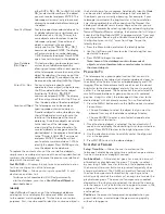
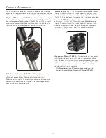
Direction Buttons
— The direction a star appears to
move in the eyepiece changes depending on which side
of the Meridian the telescope tube is on . This can create
confusion especially when guiding on a star when doing
astrophotography . To compensate for this, the direction of
the drive control keys can be changed . To reverse the button
logic of the hand control, press the MENU button and select
Direction Buttons
from the Utilities menu . Use the Up/Down
arrow keys (10) to select either the azimuth (right ascension) or
altitude (declination) button direction and press ENTER . Select
either positive or negative for both axes and press ENTER to
save . Setting the azimuth button direction to positive will move
the telescope in the same direction that the telescope tracks
(i .e . towards the west) . Setting the altitude buttons to positive
will move the telescope counterclockwise along the DEC axis .
Goto Approach
— lets the user define the direction that the
telescope will approach when slewing to an object . This allows
the user the ability to minimize the effects of backlash when
slewing from object to object . Just like with
Direction Buttons
,
setting
GoTo Approach
to positive will make the telescope
approach an object from the same direction as tracking (west)
for azimuth and counterclockwise in declination . Declination
Goto approach will only apply while the telescope tube is on
one side of the Meridian . Once the tube passes over to the
other side of the Meridian, the Goto approach will need to
be reversed .
To change the Goto approach direction, simply choose Goto
Approach from the Scope Setup menu, select either Altitude or
Azimuth approach, choose positive or negative and
press ENTER .
In order to minimize the affect of gear backlash on
pointing accuracy, the settings for Button Direction
should ideally match the settings for GoTo Approach. By
default, using the up and right direction buttons to center
alignment stars will automatically eliminate much of the
backlash in the gears. If you change the Goto approach
of your telescope it is not necessary to change the Button
Direction as well. Simply take notice of the direction the
telescope moves when completing its final goto approach.
If the telescope approaches its alignment star from the
west (negative azimuth) and clockwise (negative altitude)
then make sure that the buttons used to center the
alignment stars also move the telescope in the
same directions.
Autoguide Rate
— Allows the user to set an autoguide rate
as a percentage of sidereal rate . This is helpful when
calibrating your telescope to a CCD autoguider for long
exposure photography .
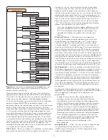
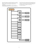
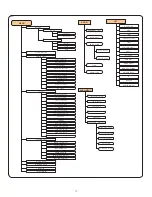
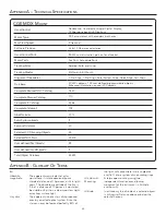
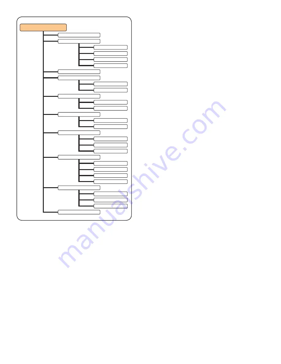
SCOPE SETUP
SET UP TIME -SITE
ANTI-BACKLASH
FILTER LIMITS
DIRECTION BUTTONS
GOTO APPROACH
AUTOGUIDE RATES
OTA ORIENTATION
MERIDIAN
MOUNT SETTINGS
RA POSITIVE
RA NEGATIVE
DEC POSITIVE
DEC NEGATIVE
RA BUTTONS
DEC BUTTONS
RA LIMITS
RA APPROACH
DEC APPROACH
RA RATE
DEC RATE
NORMAL
EAST
WEST
FAVOR CURRENT
FAVOR WEST
FAVOR EAST
DISABLED
CONE VALUE
DEC INDEX
RA INDEX
Summary of Contents for CGEM DX
Page 1: ...INSTRUCTION MANUAL CGEM DX Computerized Mount ENGLISH...
Page 29: ...27 Appendix D Maps Of Time Zones...
Page 30: ...28...
Page 31: ...29 Sky Maps...
Page 32: ...30...
Page 33: ...31...
Page 34: ...32...
Page 35: ...33...
Page 36: ...34...


