


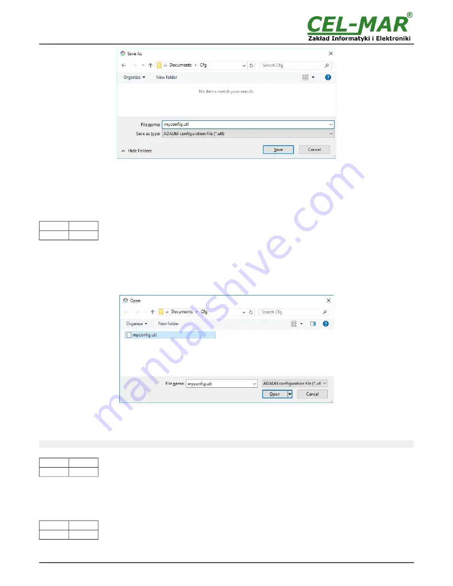
Fig 10. Saving of module configuration
5.5. PRINTING OF CONFIGURATION
To print the main configuration and measurement channels, select in left window the branch
Configuration => Communication =>
ADA-401WP => Measuring Channels
and then select from the menu
Configuration =>Print or Print View.
5.6. FIRMWARE UPDATE
Set the SW1 micro switch to configuration mode – table below
SW1-1
SW1-2
ON
OFF
Yellow LED will blink with frequency 1 Hz
(the yellow LED is located alongside the SW1 switch, under the upper terminal block
connector cover).
Run
ADAUtil
software and select
Configuration => Communication
on left panel and on right select COM port used for changing
software. Then select
Configuration => Communication => ADA-401WP
and press button
Change Firmware
, window will open in
which should be selected and opened the *.bin. Software will be load to
ADAUtil
buffer storage and will be checked. If the
ADAUtil
not
detect errors in loaded file, can be changed the module software. Process of software update is visualized by
ADAUtil
in use of
Progress Window and after proper update confirmed by correct message.
Fig. 11. Choice of software file
During loading software the yellow LED located beside SW1 micro-switch will blink, showing data flow to module. If the software
loaded correctly yellow LED will be blink with frequency 1 Hz.
Attention! Do not turn off the power during the firmware updating.
After that set micro switch SW1 to run mode as shown in the table below.
SW1-1
SW1-2
OFF
OFF
Yellow LED will be OFF.
5.7. EMERGENCY FIRMWARE UPDATE
In the case of the unsuccessful update of the module software, try again according to description in point
FIRMWARE UPDATE
. If the
update is still incorrect use emergency firmware update.
Set the SW1 microswitch to Emergency Firmware Update
mode as in the table below.
SW1-1
SW1-2
ON
ON
Restart the module by turning OFF, and after while, turning ON.
The yellow LED will light continuously and the module will be in
emergency software mode and now follow the description below:
15
ADA-401WP


