background image

page 9

TORQUE MEASUREMENT

page 4

TORQUE MEASUREMENT

Output is available in PD, PP and C modes.  In PD and PP modes peak
data is output when ZERO is pressed or activated by the AUTO ZERO
function. In C mode, the gauge outputs data continuously 160
data/second.

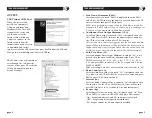
Comport signal

8 data, 2 stop, no parity. Baud Rate: 19,200 bps.

Output Connector

USB A/B  cable

Peak Data Output Format

[CAN] _ _ _ [SO] [value] _ [SI] [unit] [CR]

(_ _ _ is memory location)   

[CAN]:

ASCII control code 24

_:

Space (code 32)

[SO]:

ASCII control code 14

[value]:

Output data with sign and decimal point.  Plus sign
represents for CW torque and minus sign for CCW.
[Value] always occupy six locations and empty
locations will be filled with spaces.

[SI]:

ASCII control code 15

[unit]: 

N*m _ _ _=N.m
kgf*cm = kg.cm
lb*in _ = lb.in

[CR]:

ASCII control code 13 (Carriage Return)

Continuous Output Data Format

[CAN] [value] [CR]

GENERAL OPERATION

1. Press and hold MODE for one second to select from the follow-

ing Measuring Modes.

Real Time–

Displays torque transients (no output or indicator)

PP Mode–

Peak, captures peak torque (peak data output, PP
appears on the display)

PD Mode–

First Peak, capture first peak value (peak data
output, PD appears on the display)

C Mode–

Continuous RS-232 output Display and output
torque transients (180 data/sec., C appears on
the display)

2.   Insert Phillips tip into the screwdriver.
3. To select ratchet operation turn the ratchet one

click clockwise or counter-clockwise from the
center position. To disable ratcheting, turn it so
the semi circle is in the center position.

4. Press the CLEAR button on the display unit to

zero the display. Insert the screwdriver tip into
the screw, hold perpendicularly (not at an
angle), and turn to measure.

5. After measuring, press CLEAR to zero the display for the next test.

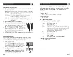
PROGRAMMING

Press POWER to turn on. Press PRG for one second. The display
shows, "HI" and then the High setpoint value.  This confirms the
tester is ready for the following programming steps.

1.

High Setpoint (HI)

After "HI" is displayed and the High setpoint
value, press DOWN 

to move the numeric

place and press UP 

to select values i.e. 50.0

for 50.0 lbf-in, then press PRG 

to enter. 

2.

Low Setpoint (LO)

After High value is entered, "LO" is displayed,
then the Low setpoint value. Press DOWN to
move the numeric place and press the UP to
select values, then press PRG to enter.

8

7

6

Summary of Contents for DID-4

Page 1: ...t prepaid The foregoing warranty constitutes the SOLE AND EXCLUSIVE WARRANTY and we hereby disclaim all other warranties express statutory or implied applicable to the products and or software including but not limited to all implied warranties of merchantability fitness non infringement results accuracy security and freedom from computer virus In no event shall Imada Inc and or its affiliated com...

Page 2: ... 100ºF Do not apply torque exceeding the rated capacity 35 lbf in regardless of whether the unit is On or Off Avoid shock load When charging the battery be sure to use the provided AC adapter charger exclusively Do not use lacquer thinner or any solvent to clean the unit Do not disassemble or modify the unit Digital Torque Tester Screwdriver Model DID 4 List of Equipment DIgital Torque Tester Scre...

Page 3: ...AC charger adapter receptacle RESET System reset button 1 2 3 4 5 6 7 8 9 10 6 7 8 9 10 2 1 3 4 5 Measuring range 2 0 560 0 ozf in 0 20 35 00 lbf in 0 20 40 00 kgf cm 2 0 400 0 N cm 0 2 4 000 N m Accuracy 0 5 F S 1 LSD Display 4 digit LCD Operation CW CCW and fixed position Measuring modes PP Peak Mode displays PEAK torque value that will not change until a higher value is measured PD Peak Down Mo...

Page 4: ...t PP appears on the display PD Mode First Peak capture first peak value peak data output PD appears on the display C Mode Continuous RS 232 output Display and output torque transients 180 data sec C appears on the display 2 Insert Phillips tip into the screwdriver 3 To select ratchet operation turn the ratchet one click clockwise or counter clockwise from the center position To disable ratcheting ...

Page 5: ... place and press the UP to select values then press PRG to enter CLO sets the start and stop trigger points for Continuous data output When torque reaches the CLO value the tester starts to output data and stops if torque falls below the value Note the display does not show any value below the CLO minimum 5 Auto Zero Reset AC After Continuous Data Output Minimum is entered AC is dis played then th...

Page 6: ...on and value Clearing Data from Memory Single clear Press MEM then press UP or DOWN to move to a memory location When the desired memory value is displayed press CLR CLR is displayed Press CLR again to clear the data and is displayed to confirm deletion All clear Press CLR and hold until the display shows ALL then press CLR again and is displayed to confirm deletion Downloading Memory Data 1 Press...

Reviews: