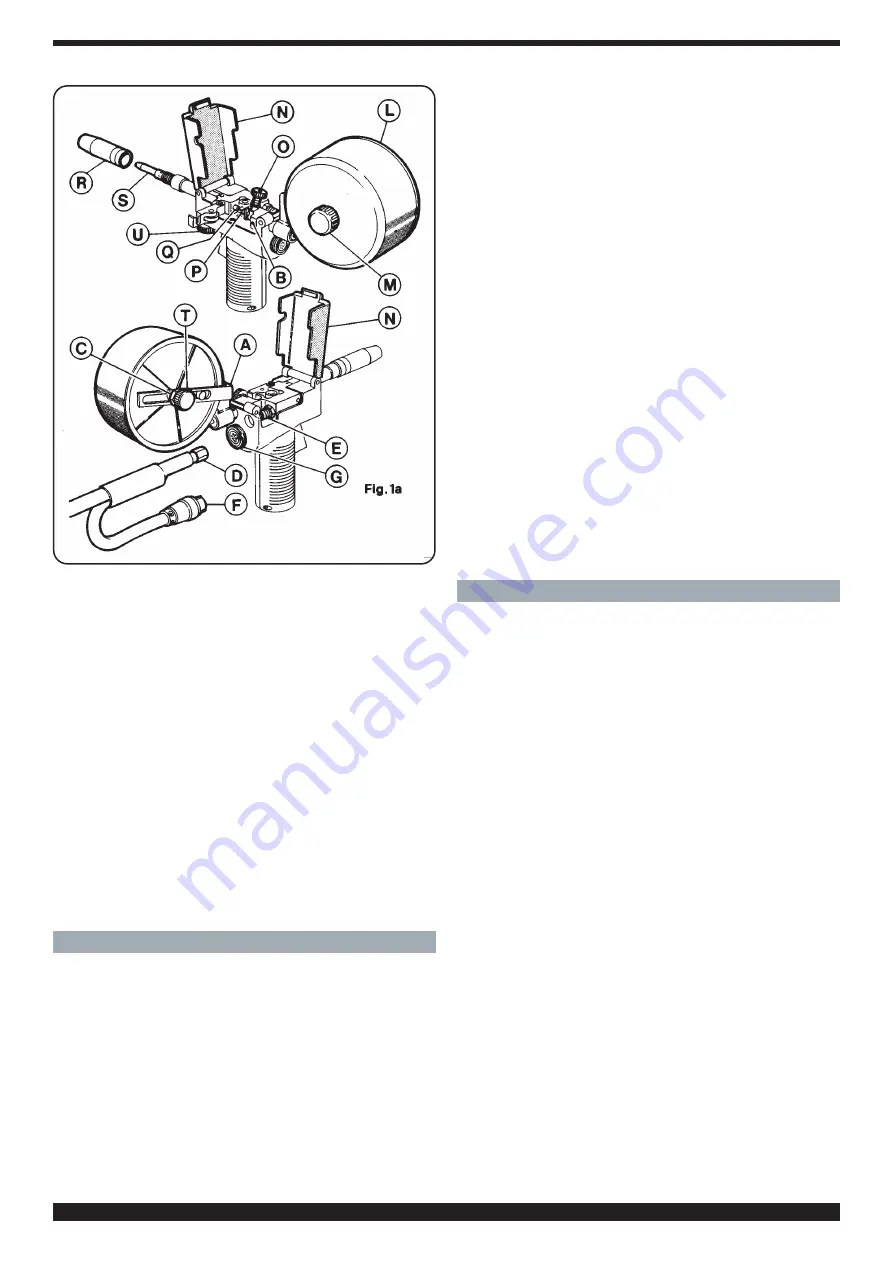
Cebora JAW-FEED Instruction Manual Download Page 6

6

A)

Spool Support

B)

Lock screw

C)

Lock nut

D)

Fitting

E)

Fitting

F)

Connector

G)

Connector

H)

Fitting

I)

Connector

L)

Spool cover

M) Knob
N)

Spool cover

O)

Roller presser pin

P)

Teflon tube

Q)

Teflon tube

R)

Gas nozzle

S)

Contact tip

T)

Knob

U)

Wire speed control knob.

4. INSTALLATION

4.1 INSTALLING THE SPOOL-GUN ART 1562

This spool-gun has been designed for use with genera-
tors art. 582 and art. 584 using the extension cable art.
1324. Other set-ups may be used provided that the com-
ponents are compatible.
Turn the spool support (A) to the position required and
lock it in position using the lock screw (B).
Depending on the welding type and location, it may be
necessary to change the maximum rotation angle of the
spool support (A). To change the angle of the spool sup-

port, loosen the lock nut (C) and move the spool contain-
er along the support slot.
Using the spanner supplied, screw the fitting (D) of the
extension cable (art. 1324) to the union (E) of the spool-
gun. Connect the connector (F) of the extension cable to
the connector (G) of the spool-gun.
Connect the extension cable (art. 1324) to the generator
following the instructions given in section 3.5. E2. of the
generator instruction manual.

4.2 INSTALLING THE JAW-FEED WIRE FEED UNIT
ART 1428

This jaw-feed wire feed unit has been designed for exten-
sion to generators art. 582 and art. 584 using the exten-
sion cable art. 1324. Other set-ups may be used provid-
ed that the components are compatible.
Screw the fitting (D) of the extension cable (art 1324) to
the wire feed unit fitting (H). Plug the connector (G) of the
extension cable into the wire feed unit connector (I).
Connect the extension cable (art. 1324) to the generator
following the instructions given in section 3.5.E2. of the
generator instruction manual.
Select a wire-feed roller with a suitable groove. Fit the
wire spool. Insert the wire into the wire drive motor and
ensure that the wire-feed roller groove and the wire are
aligned.
Connect up the welding torch.

5. WELDING GUIDELINES

5.1

MILD STEEL WELDING

To weld mild steel use 75% Argon + 25% CO2 or 100%
CO2. 
Select the welding voltage you require by means of the
welding voltage switch on the generator.
Approach the point to be welded and press the torch
push button (70).
• Adjust the potentiometer (U) (see figs. 1a and 1b) until
the welding noise is constant and continuous.
If the speed is too high, the wire will tend to get stuck on
the workpiece causing the torch to bounce back.
If the speed is too slow, the wire will melt irregularly or
else the arc will switch off.
When you have finished welding, switch off the machine
and shut off the gas bottle.
For the correct welding angle, see figure 2.

5.2 ALUMINIUM WELDING 

The machine set-up for aluminium is the same as that for
mild steel with the following differences:
1.100% Argon as welding protection gas.
2. Wire of composition suitable for the material to be
welded.
- To weld ALUMAN, use 3÷5% silicon wire.
- To weld ANTICORODAL, use 3÷5% silicon wire.
- To weld PERALUMAN, use 5% magnesium wire.
- To weld ERGAL, use 5% magnesium wire.

Note for Jaw-feed wire feed unit art.1428
If you are using a torch suitable for steel wire welding, the
same must be modified as follows: 

Summary of Contents for JAW-FEED

Page 1: ...et sch mas l ctriques Piezas de repuesto y esquemas el ctricos Pagg Seiten sel 22 27 I MANUALE DI ISTRUZIONI SPOOL GUN E JAW FEED PAG 2 GB INSTRUCTION MANUAL SPOOL GUN AND JAW FEED Page 6 D ANLEITUNGS...

Page 2: ...iste dalla legge PACE MAKER I campi magnetici derivanti da correnti elevate possono inci dere sul funzionamento di pacemaker I portatori di apparec chiature elettroniche vitali pacemaker dovrebbero co...

Page 3: ...lla con nessione al connettore I del carrello Per collegare la connessione art 1324 al generatore seguire le istruzioni riportate sul manuale del generatore stesso al punto 3 5 E2 Scegliere il rullo t...

Page 4: ...rice deve essere predisposta come per la saldatu ra dell acciaio dolce applicando le seguenti varianti Bobina di filo di acciaio inossidabile compatibile alla composizione dell acciaio da saldare Bomb...

Page 5: ...RS The magnetic fields created by high currents may affect the operation of pacemakers Wearers of vital electronic equip ment pacemakers should consult their physician before beginning any arc welding...

Page 6: ...able art 1324 to the wire feed unit fitting H Plug the connector G of the extension cable into the wire feed unit connector I Connect the extension cable art 1324 to the generator following the instru...

Page 7: ...the correct welding angle see figure 2 5 3 STAINLESS STEEL WELDING The machine set up for stainless steel is the same as that for mild steel with the following differences Stainless steel wire compati...

Page 8: ...MU F R DIE GESAM TE LEBENSDAUER DES GER TS AN EINEM ALLEN INTE RESSIERTEN PERSONEN BEKANNTEN ORT AUFBE WAHRT WERDEN DIESES GER T DARF AUSSCHLIE LICH ZUR AUSF HR UNG VON SCHWEI ARBEITEN VERWENDET WERD...

Page 9: ...s Art 1324 an den Stromerzeuger entsprechend den Anweisungen des Abschnittes 3 5 E2 der Bedienungsanleitung des Strom erzeugers vornehmen Drahtvorschubrolle mit geeigneter Nut w hlen Drahtrolle montie...

Page 10: ...deten Schwei drahtes entsprechen Spezielle Schleifscheiben und B rstvorrichtungen f r Alu minium einsetzen und diese nicht f r andere Materialien verwenden BEACHTEN SIE Sauberkeit bedeutet Qualit t Di...

Page 11: ...gn tiques g n r s par des courants lev s peuvent affecter le fonctionnement des stimulateurs car diaques Les porteurs d appareils lectroniques vitaux sti mulateurs cardiaques devraient consulter le m...

Page 12: ...connecteur G de la connexion au connecteur I du d vidoir Pour raccorder la connexion art 1324 au g n rateur suivre les instructions figurant sur le manuel du g n rateur au point 3 5 E2 Choisir le rou...

Page 13: ...n de soudure voir la figure 2 5 3 SOUDURE DE L ACIER INOXYDABLE Le poste souder doit tre pr par e comme pour la soudu re de l acier doux en appliquant les variantes suivantes Bobine de fil d acier ino...

Page 14: ...EL CONTE NIDO DE ESTE MANUAL Y CONSERVARLO DURANTE TODA LA VIDA OPERATIVA EN UN SITIO CONOCIDO POR LOS INTERESADOS ESTE APARATO DEBER SER UTILIZADO EXCLUSIVAMENTE PARA OPERACIONES DE SOLDADURA 1 PRECA...

Page 15: ...rt 584 por medio de la conexi n art 1324 pueden emplearse sistemas distintos siempre y cuando sean compatibles Enroscar el empalme D de la conexi n art 1324 con el emplame H del carrito y conectar el...

Page 16: ...ldadura Hay que utilizar muelas y cepillos adecuados para el alu minio que a su vez no deber n usarse nunca sobre otros materiales Recuerden que limpieza significa calidad Las bobinas de hilo deben co...

Page 17: ...QUALIFICATO THIS PART IS INTENDED SOLELY FOR QUALIFIED PERSONNEL DIESER TEIL IST AUSSCHLIE LICH F R DAS FACHPERSONAL BESTIMMT CETTE PARTIE EST DESTINEE EXCLUSIVEMENT AU PERSONNEL QUALIFIE ESTA PARTE...

Page 18: ...OSS SHAPED NUT 22 ROSETTA IN ALLUMINIO ALUMINIUM WASHER 23 BOCCOLA IN GOMMA RUBBER BUSHING 24 PERNO PORTA BOBINA SPOOL SUPPORT PIN 25 PERNO FILETTATO THREATED PIN 26 MANOPOLA KNOB 27 PERNO CUSCINETTO...

Page 19: ...19 SPOOL GUN ART 1562...

Page 20: ...TION 21 CONNETTORE CONNECTOR 22 SOPPORTO ASPO SPOOL HOLDER SUPPORT 23 PERNO IN OTTONE BRASS PIN 24 PRESA SOCKET 25 DADO NUT 26 ELETTROVALVOLA SOLENOID VALVE 27 RESCA FITTING 28 PASSACAVO GROMMET 28 IN...

Page 21: ...21 JAW FEED ART 1428...

Page 22: ...LU BLUE K MARRONE BROWN J ARANCIO ORANGE I ROSA PINK CODIFICA COLORI WIRING DIAGRAM CABLAGGIO ELETTRICO COLOUR CODE L ROSA NERO PINK BLACK M GRIGIO VIOLA GREY PURPLE N BIANCO VIOLA WHITE PURPLE O BIAN...

Page 23: ...23 JAW FEED ART 1428...

Page 24: ...24...

Reviews: