PROGRAMMING.
The receiver cannot be controlled directly without prior programming.
Once finished, it will be stored even without power, and it will not be eliminated until it is replaced by a new one.
IMPORTANT.
Install receiver antenna before programming
Pairing with sending unit.
Each receiver admits up to a maximum of 5 Cebek transmitters from group 3 R.F., which pair it exclusively with them, avoiding
remote activation from any other external transmitter.
From the factory, the receiver is supplied blank, without associated codes, so it must be programmed so that the specific
transmitter can interact.
When pairing the relay with a button on the transmitter, the combination established in the dips is also stored, and the
corresponding type of operation is assigned to the relay, which can be selected from three different types: bistable, monostable or
timed.
Programming is achieved simply by performing the following steps:
1. Carry out the installation of the antenna and power supply of the receiver. Without connecting the load.
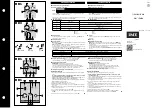
2. Set the Dip combination that determines the type of operation that the relay will assume (fig. 3).
3. Receiver programming is started by briefly pressing the “Enter” button. The red led will light up.
4. With the receiver on standby, you only have to press the button of the transmitter to which you want to associate. The transmitter
button must be kept closed until the LP0 led performs three cycles of flashing and fixed, (necessary process to correctly read and
identify the transmitter button). This operation could take a few seconds.
5. Programming is confirmed by briefly pressing the receiver's “Enter” button again or waiting 20 seconds. The red led will turn off.
Next relay. To program the next relay, the programming process must be restarted again from point 1. However, when the led of the
first relay lights up, briefly press Select, the new relay will be selected and its corresponding led will light up. From that moment on,
the rest of the process must simply be completed.
The memory is FIFO, so from the pairing with 5 transmitters, the next programmed will occupy the memory that was allocated to
the first, another one would replace the memory initially allocated to the second and so on consecutively.
If a timed operation is configured, the relay also stores the position of the “Time” potentiometer. The complete travel of the
potentiometer is established between the margins of the scale selected in Dip. The specific potion of the potentiometer will be the
one that will establish the exact timing time.
FUNCTIONING.
In the rest state, the receiver relay will be inactive, maintaining the connection between the “Common” and “Nc” contacts. When the
relay is activated, it will switch the connection of the contacts to internally link the “Common” with the “No” , allowing current to flow
to the load.
Each relay will respond independently to bistable, monostable or timed operation, as programmed.
Reset.
When activating Reset, the relay will become inactive, abandoning any previous order. As long as Reset is pressed, the
relay will not respond to any order from the transmitter.
Biestable.
The transmitter button assumes the operation of a switch, activating or deactivating the relay alternately with each
press. As long as a new pulse does not occur, the state in which the relay is found will remain unchanged.
Monoestable.
As long as the transmitter button is kept closed, the relay will be activated, deactivating when the button is
released.
Timer.
The relay will be activated when the transmitter button is closed. Timing, however, will start when the button is released, at
which point it will start and after which the relay will deactivate.
2
TL-602
Figure 3 Configuration Dip
* Response relay operation
monostable
timer
timer
timer
timer
biestable


