6] OUTPUT FORMATS 26, 30 ET 44 BITS WIEGAND
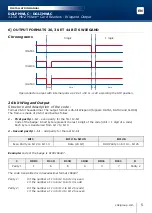
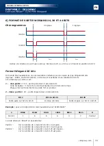
Chronograms
Open collector output with internal pulls up 1K at +5V or +12V according the ST4 position.
26-bit Wiegand Output
Structure and description of the code :
Format 26-bit hexadecimal. The output format is 26-bit Wiegand (Signals: DATA1, DATA0 and CLOCK)
The frame is made of 26-bit and built as follow:
1 - First parity:
1-bit – even parity for the fi rst 12-bit
Code of the badge: 6 half byte represent the last 6 digit of the code (4bit = 1 digit of a code)
Each byte is transferred from bit 7 to bit 0.
2 - Second parity:
1-bit – odd parity for the last 12-bit
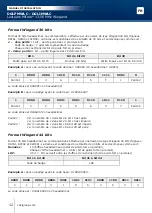
Bit 1
Bit 2 to bit 25
Bit 26
Even Parity on bit 2 to bit 13
Data (24 bit)
Odd Parity on bit 14… bit 25
Example:
code of the badge is 0100166A37.
1
0001
0110
0110
1010
0011
0111
0
Parity 1
1
6
6
A
3
7
Parity 2
The code transmitted is in hexadecimal format 166A37
Parity 1:
0 if the number of 1 in bit 2 to bit 13 is even
1 if the number of 1 in bit 2 to bit 13 is odd
Parity 2:
0 if the number of 1 in bit 14 to bit 25 is odd
1 if the number of 1 in bit 14 to bit 25 is even
0 logic
\DATA1
\CLOCK
\DATA0
50 μs
50 μs
2ms
2ms
1 logic
5
cdvigroup.com
EN
DGLPMWLC - DGLIMWLC
13.56 MHZ Mifare
®
Card Readers - Wiegand Output
INSTALLATION MANUAL


