


INDEX
Warnings & Safety Checklists…..………….Inside Front Cover
Specifications…………………………………………………… 1
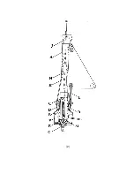
Drawing………………………………………………………….. 2
Parts List………………………………………………………… 3
Uncoiling and Straightening the Luff.……………………..4 – 5
Assembly……………………………………………………..5 - 9
Installing the Furling Line…………………………………10 - 11
Hoisting the Jib…………………………………………….11 - 12
Lowering the Jib………………………………………………..12
Sailing with your Furler………………………………….. 12 - 13
Trailering Instructions…………………………………… 13 - 14
Maintenance & Storage…………………………………….… 14
Sailmaker’s / Rigger’s Instructions………………………….. 15
Warranty…………………………………………….. Back Cover
SPECIFICATIONS
Headstay Length 29 feet, maximum
Wire Size
1/8”, 5/32”, 3/16”
Headstay Fittings There must be a toggle at both ends of the
headstay. The turnbuckle must be a ¼” or
5/16” swage on turnbuckle with a T-bolt and
toggle on the bottom (see page 5).
It
MUST
be locked by cotter pins
. You may NOT use
3-piece (Navtec) turnbuckles. The stud
must NOT have non-marine protuberances
(such as aircraft hex nuts). If your
turnbuckle doesn’t meet
all
of the above
requirements, replace it with one that does.
Mounting
The system can NOT be mounted above
the turnbuckle. If you wish to raise the
system for better clearance, shorten the
stay and use link plates below the
turnbuckle.
Furling Line
5/32” or 3/16” braid on braid dacron. If you
prefer a larger diameter, you should de-
core the portion of line forward in the
cockpit. (Otherwise the larger line won’t fit
onto the furling drum.)
(1)
Summary of Contents for FLEXIBLE FURLER 2
Page 4: ... 2 ...


