background image

3

960-Hour Time Lapse Video Cassette Recorder

6

Power Loss indicator : 

Flashes on after power loss.

7

CNT indicator : CNT

Comes on when the tape or alarm counter is on.

8

SPD indicator :  SPD

Comes on when the play or recording speed is on.

9

RMC.L indicator  :  RMC.L

Comes on when the RMC LOCK sw is set to the “ON”
position.

10 S.REC indicator : S.REC

Comes on when “YES” is selected in the menu for the
series recording.

11 R.REC indicator  :  R.REC

Comes on when “YES” is selected in the menu for the
repeat recording.

12 SET LOCK SW indicator : 

Comes on when the SET LOCK sw is set to the “ON”
position.

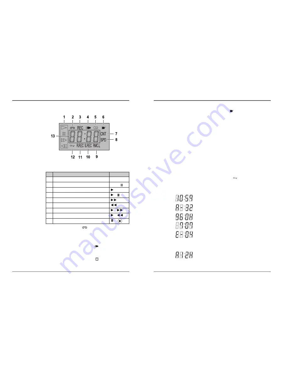
13 Mode display

• TAPE COUNTER display (ex:10:HOUR,59:MINUTE)

- Maximum Hour : 19  - Maximum Minute : 59 

• ALARM COUNTER display (ex: A:Alarm , 32:Alarm No.)

• PLAY/REC SPEED display (ex: 960H:Play/Recording

Speed)

• TIME display (ex: 7:HOUR , 07:MINUTE)

• ERROR display (ex: E:Error , 04:Error No.)

- E-01 : The cassette cannot be loaded or unloaded.
- E-02 : The tape stops.
- E-03 : The drum can not rotate properly.
- E-04 : The tape is cut/broken.

• AUDIO ON display (ex: A:Audio , 12H:Play Speed)

2

960-Hour Time Lapse Video Cassette Recorder

Digital Display

1

Operation Indicators

They display the actual operation mode.

2

Cassette indicator :

Comes on when a cassette is loaded.

3

Record check indicator :  REC

Flashes on during record check

4

Alarm or Panic indicator :  

Flashes on when an alarm or panic is being recorded and
stops flashing after alarm recording.

5

Timer Recording indicator :

Comes on when in timer recording stand-by mode, or
during a timer recording.

Operation Mode

Indicator

1 Record(REC)

REC

2 Record pause (REC PAUSE)

REC + 

3 Playback (PLAY)
4 Still image (STILL)

+

5 Fast forward (FF)
6 Rewind (REW)
7 CUE(CUE)

+

8 Review(REVIEW)

+

9 Slow(Pause Still + FF, Pause Still + REW)

+

Summary of Contents for JT960

Page 1: ...rder User s Guide JT960 Be sure to read carefully and follow all the SAFETY INFORMATION on pages i ii iii Keep the manual in a safe place for future reference TIME LAPSE RECORDER CCTV IMPORTS 960 HR w...

Page 2: ...sibility too This sheet lists important information that will help to assure your enjoyment and proper use of the video product and accessory equipment Please read them carefully before operating and...

Page 3: ...video dealer or local power company For video products intended to operate from battery power or other sources refer to the operating instructions 6 Overloading Do not overload wall outlets of extensi...

Page 4: ...ndicators 1 Front panel 1 Digital display 2 Back panel 4 Connections 5 Types of on screen displays and Display Sequence 6 Video Cassettes Tapes 8 Setting the Clock 9 Changing the on screen display 11...

Page 5: ...960H Play Recording Speed TIME display ex 7 HOUR 07 MINUTE ERROR display ex E Error 04 Error No E 01 The cassette cannot be loaded or unloaded E 02 The tape stops E 03 The drum can not rotate properl...

Page 6: ...refer to the manuals accompanying all other devices If the connections are not made properly it may cause a fire or damage the equipment 4 960 Hour Time Lapse Video Cassette Recorder Back Panel 1 AC P...

Page 7: ...imes the setting procedure is now completed and the normal screen is displayed During recording or playback the menus cannot be displayed Press the MENU button First time Press the SHIFT button to mov...

Page 8: ...ead screwdriver to break off the erasure prevention tab on the cassette To record again on a tape without erasure prevention tab cover the hole with adhesive tape Erasure prevention tab To prevent acc...

Page 9: ...ayed 4 Press the SHIFT button until the arrow mark points Display set 5 Press the SHIFT button to select Display Set then the DISPLAY SET menu is displayed 6 Press the SET or button to set the minutes...

Page 10: ...R will go into stop mode to avoid damage to the tape If you playback the recorded part where recording check was performed noise may appear If you change the recording speed during recording noise or...

Page 11: ...r will light on the display panel The VCR is now in timer recording stand by mode If the set stop time is earlier than or the same time as the set start time the VCR will consider the stop time to be...

Page 12: ...hed and will be flashing on the display panel The VCR internal battery is completely charged after the VCR has been connected to an AC power outlet for 48 hours and it will maintain all the VCR settin...

Page 13: ...HIFT button until the arrow mark points to Alarm Rec Set 4 Press the SHIFT button to display the ALARM REC SET menu 5 Press the SHIFT button to select YES or NO YES The alarm recording takes place whe...

Page 14: ...nect 2 VCRs or more as illustrated below 2 Set the following items as indicated Panic Recording This feature is similar to an alarm recording but the recording time is not pre selected When there is a...

Page 15: ...place R REC will light on the display panel 4 Press the Menu button two times the normal screen is displayed The setting procedure is now complete 5 Press the REC button Recording will start When the...

Page 16: ...ecording check operations recording is suspended momentarily Normal Playback Normal Playback 1 Turn on the power to the TV monitor 2 Load the video cassette tape 3 Press the REC PLAY SPEED or button t...

Page 17: ...The display returns to the normal screen The VCR will advance or rewind the tape at high speed and playback the first 5 seconds of every normal recording To cancel the index search mode press the STOP...

Page 18: ...LD Other Functions Tape Counter Zero Search Using the counter it is easy to find a desired recording 1 Press the CLEAR button at the beginning of the desired recording The counter will be reset to 0H...

Page 19: ...arm recordings past 35 is erased POWER LOSS the number of power losses and the date and time of the 35 most recent power losses and recoveries are displayed 7 Press the MENU button the normal screen i...

Page 20: ...PEN Switch Circuit If the input becomes 0V for 500 msec or more the VCR starts panic recording TAPE END OUT Terminal 1 High During recording when the end of the tape is reached the output becomes DC 5...

Page 21: ...switch input of devices like a camera switching unit or a quad compressor 1 Low 2 High SERIES OUTPUT Terminal During recording when the end of the tape is reached the output becomes DC 5V SERIES INPU...

Page 22: ...the TV monitor is correct 3 Check that the on screen display of the date and time is correct 4 Press the REW button to rewind the recorded tape a few seconds 5 Press the PLAY button and check that th...

Page 23: ...at all try the following 1 Unplug the power cord then plug it back in 2 Reset the memory Press the RESET button Under normal conditions do not touch the RESET button 3 If the problem is not corrected...

Page 24: ...solution Black white mode 300 lines Color mode 250 lines Audio Input RCA pin jack more than 47k 8 8dBm unbalanced Output RCA pin jack less than 1 5k 7 8dBm unbalanced Microphone input 60 dBs 3 5mm min...

Reviews: