background image


  4/8-channel H.264 DVR User Manual 


1.5 Product appearance and interface definition   

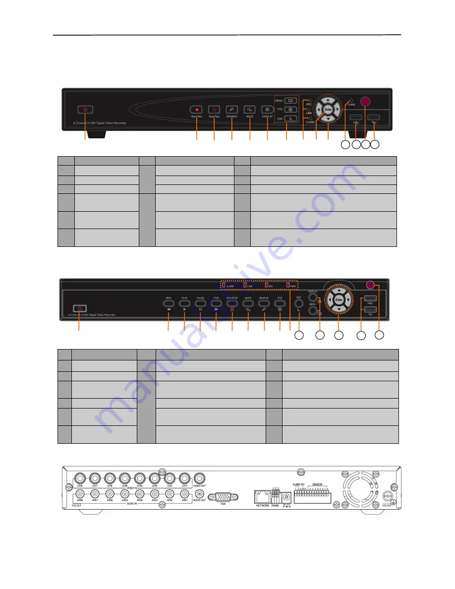
1.5.1 Front panel   

Front panel 1   


Front panel 2 


1.5.2 Back panel   


No.


Definition 

No.


Definition 

No.


Definition 

1


Power switch 

MENU: Main menu 

Confirm 

2


Manual recording 

PTZ: PTZ control 

10 

Directional keys: up, down, left and right 

3


Stop recording 

ESC: Exit/Return 

11 

Power LED 

Video search 

REC: Video recording 

indicator 

12 

  2.0 USB interface, which can be accessed 

to USB disk for backup or upgrade 

Mute 

LINK: Network 

connection indicator 

13 

Remote control infrared receiver 

Display mode 

ALARM: Alarm 

indicator 

14 

USB mouse interface 

No. 

Definition 

No. 

Definition 

No. 

Definition 

1   

Power switch 

Mute 

PTZ control 

Rewind 

Video search 

11 

Exit/Return 

Play 

10 

ALARM:Alarm indicator 

12 

DISPLAY:Display mode


MENU:Main menu   

Pause 

LINK:Network connection indicator  13 

up, down, left , right and Confirm 

Foward 

REC: Video recording indicator 

14 

USB PORT: Used for connecting 

USB to backup, upgrade and mouse 

Manual start/stop 

recording 

PWR: Power LED 

15 

Remote control infrared receiver 


11


12


13


14


12


15


11


13


14


Summary of Contents for JE-D7004

Page 1: ...1 4 8 channel Embedded Digital Video Recorder...

Page 2: ...7 2 3 System login 7 2 4 Shortcut menu 8 Chapter 3 Advanced settings 10 3 1 Main menu 10 3 2 Recording mode 11 3 3 Video search 12 3 4 Backup 13 3 5 Hard disk management 14 3 6 Basic setup 15 3 7 Adv...

Page 3: ...264 DVR User Manual ii 4 10 System setup 35 4 11 Host info 35 Chapter 5 Client software Player 36 5 1 Client software 36 5 2 Video Player 36 Appendix 1 Q A 41 Appendix 2 hard disk space occupation ca...

Page 4: ...l shall be 15cm or more away from other objects or wall to facilitate fan cooling The DVR shall work under temperature humidity and voltage according to its technical specifications The space where DV...

Page 5: ...e of product instruction One piece of SATA hard disk data cable installed in the host One DC12V3A power adapter Support HDD already installed and a set of mounting screws One piece of HDD power cable...

Page 6: ...k backup moved hard disk backup network backup backup by files backup by time Network transmission 4 8 channels real time network transmission with CIF resolution Capture function Support Email alarm...

Page 7: ...to USB disk for backup or upgrade 5 Mute LINK Network connection indicator 13 Remote control infrared receiver 6 Display mode ALARM Alarm indicator 14 USB mouse interface No Definition No Definition...

Page 8: ...in Connect active audio signals such as pickup 4 Audio out Connect the audio output 5 VGA Connect VGA monitor such as computer monitor 6 NETWORK Connect the Ethernet 7 RS485 Connect the RS485 interfac...

Page 9: ...er keys PTZ PTZ Control Single and multi split screen Quit shortcut menu Shortcut menu Direction buttons Next on the left and right OK ESC Exit Return MENU Enter the main menu STARTREC Start recording...

Page 10: ...ol is available if clicking direction or and icon There is a volume bar in volume control interface Move mouse to a position and click right button the corresponding volume will be shown in the right...

Page 11: ...t record mode is on or boot time is in the setting time the system will start automatic recording function the REC indicator will be on to indicate the system is working normally Note 1 If hard disk i...

Page 12: ...rol and video recording 2 4 1 Main menu Click Main Menu to enter the main menu interface please see 3 1 2 4 2 Lock When the password function is on please see 2 3 click right button in monitoring inte...

Page 13: ...to set the second location Step 5 Select the APPLY button to save the settings END Note 1 If you need to set up more points repeat steps 2 5 2 to view the point has been set in the current point ente...

Page 14: ...AYBACK RECORD HDD BASIC ADVANCED and Exit options as shown below Note The setup of all the submenus below will not be effective until Enter is pressed The setup of this menu will be invalid if you exi...

Page 15: ...this unit is energized It works only if the corresponding channel is enabled in the Channel option BY TIME performing recording as scheduled When timing recording is selected the Record Time Configura...

Page 16: ...rm recording and the background color indicates no recording Click a date on this bar to search the record information of every hour of that day The search results will be visualized in the Day bar be...

Page 17: ...Slow for slow play press Fast Forward or Fast Backward for fast forward or backward play or press Pause Frame for pause or frame by frame play press Exit to exit from the playback screen and return t...

Page 18: ...e hard disk state will be ONLINE ALL FREE referring to the total storage capacity and current remaining storage capacity of the hard disk TIME LEFT referring to the time remaining for recording based...

Page 19: ...he Basic Setup screen includes the 6 options of System Language Time Setup User Password Display Setup Video Audio Setup and Exit 3 6 1 System language Move the cursor to the LANGUAGE option the icon...

Page 20: ...set the user password Admin password This option is operated with keys or the mouse Enter digits directly to set the administrator password Notes 1 This unit has no initial password When you re setti...

Page 21: ...he picture color including the 4 options of chromaticity brightness contrast and saturation Press Enter to exit and save the set parameters Preview On The picture of this channel can be seen in the Vi...

Page 22: ...ss Left Right or drag the cursor with the mouse directly to adjust the volume Note The system will restart when the VGA resolution or the camera resolution is modified 3 7 Advanced Enter the following...

Page 23: ...nel is lost this channel will display in the lower part of the Video Preview screen Video Loss ALARM MANAGE OUTPUT the time of the DVR outputting the alarm signal to the outside when an alarm is gener...

Page 24: ...the mailbox be affected due to an excess number of pictures 3 7 2 System info Enter the System Info screen from Main Menu Advanced Functions as shown below You can inquire about the software version n...

Page 25: ...el option E In the Recording Mode screen select Timing Recording in the Recording Mode option also click Record Time Configuration to enter the Record Time Configuration screen and set the correspondi...

Page 26: ...m update Copy the update file to the root directory of the U disk then insert the U disk into the USB slot of this unit and Enter this button for system updating The screen will display the progress b...

Page 27: ...confirmation After starting the system will establish a connection with the DHCP server automatically When this is successful this unit will be allocated an IP address which will be displayed on the...

Page 28: ...ocate an IP address on the same network segment If there is a router device in the network you have to set the corresponding gateway DNS setting the IP address of the domain name server DNS varies fro...

Page 29: ...message has been sent to the designated mailbox as shown below 2 Activate account Log in your mailbox and open the confirmation link sent from support dyndns com as shown below Click the link below a...

Page 30: ...Manual 26 4 Application for free domain name After entering the Dynamic DNS Services screen click Dynamic DNS Free to apply for a free dynamic domain name as shown below Enter the Dynamic DNS Free sc...

Page 31: ...e select the service type and then enter the dynamic IP address usually being the dynamic IP address of the network of the DVR host to be tied in the Add New Hostname screen as shown below Complete th...

Page 32: ...arding Port forwarding procedures 1 Set the host IP address See the relevant section 2 Log in the router If the IP address of the router is 192 168 1 1 After this IP has been entered in the IE address...

Page 33: ...4 8 channel H 264 DVR User Manual 29 Click Enter to enter the main screen of the router as shown below Click Applications Gaming as shown below...

Page 34: ...umber in the corresponding files and select Both in Protocol The tick below Enable denotes selected After setup click Save Setting to save the settings 80 stands for the WEB port 9000 for the media po...

Page 35: ...eliable site of the system For example if the IP address of the DVR is 192 168 1 100 first open IE Attributes Internet Options Security Options for an ordinary XP system as shown below This can be set...

Page 36: ...ote If the DVR host is in an LAN but you have chosen the WAN option the effect of the preview image will be non real time 4 4 Real time preview After logging in the client end successfully enter the r...

Page 37: ...record data as shown in the figure above Select the file to be played back and double click this file or click Playback to play it A control bar will appear at the bottom of the picture for pause sto...

Page 38: ...he setup method is the same as the mainframe menu See Alarm Setup in Chapter 3 for details 4 8 PTZ control Click Setup PTZ to enter the PTZ Control mode See Figure 5 6 See Chapter 3 Network Setup in t...

Page 39: ...th must be high otherwise the image may have a delay File SAVE PATH setting the record saving directory during remote recording and remote backup IE password setting the IE login password Note This pa...

Page 40: ...dress or Domain Name MEDIA PORT Enter the port number the default is 9000 PASSWORD Enter IE password NETWORD Select web styles LAN is the local area network INTERNET is the wide area network Notice Af...

Page 41: ...nel H 264 DVR User Manual 37 Click File F as shown in the following image select open the local files F When opening the root of the record file please select the format as 264 as shown in the followi...

Page 42: ...e list select one of the files to be played Click OPEN as shown in the following image Then click PLAY option as shown in the following image After clicking PLAY option click the button of the player...

Page 43: ...ard forward frame File Cut Slow Normal Fast File Deletion Next Hour avi AVI Format transmission Capture bitmap OSD Decrease video Volume Control Note 1 Double click the image to enlarge the image 2 Wh...

Page 44: ...4 8 channel H 264 DVR User Manual 40 Select the channel audio to be played then click OK as shown in the following instructions...

Page 45: ...r to Appendix 2 hard disk space calculation 6 DVR s remote controller can not work but the monitor screen is right and the panel buttons can be used properly A If the controller is pointing to the IR...

Page 46: ...work environment option in login interface for 4 channel DVR in addition to select LAN in network environment option in login interface please select ordinary in details option under recording mode 16...

Page 47: ...ble according to different bit rate and resolution The table is only for reference the real product shall prevail Unit Megabyte Channel Hour Bit rate Resolution Excellent Good Ordinary D1 400 300 200...

Page 48: ...4 8 channel H 264 DVR User Manual 1...

Reviews: