background image

ENG

-33

ENG

-32

ENG

M2/-

M1/+

M2/-

M1/+

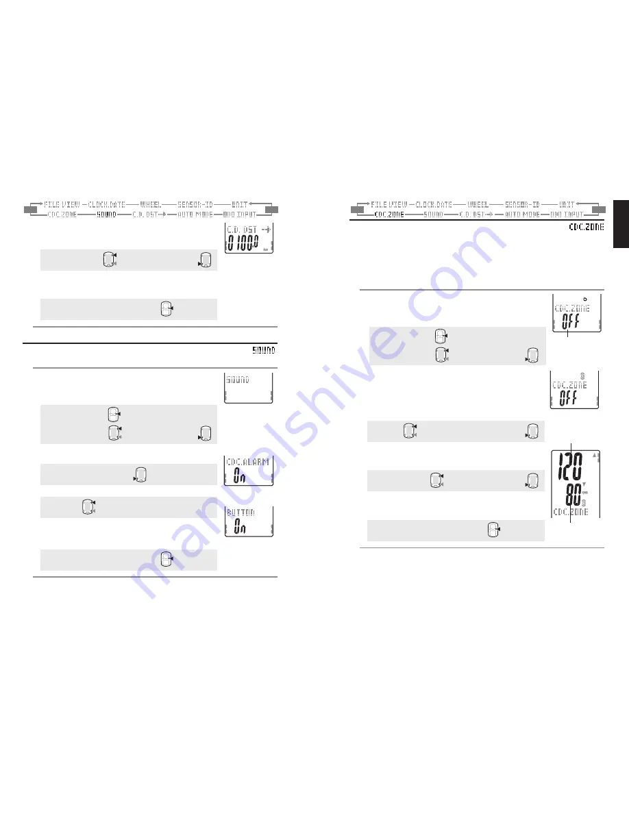
Setting the target cadence zone

You can set the target cadence zone on/off and change the upper/lower limit of the
target cadence zone.

* Stop measurement and perform the resetting operation (page 16) before you can

change the target cadence zone. Unless you perform the resetting operation, “

DATA

RESET

” appears on the screen, preventing from changing the target cadence zones.

* For details of the target zone, see “Use of the target zone” (page 34).

1. Press the 

MENU

 button in the measurement screen to

switch to the menu top screen.
Switch to the 

CDC.ZOne

 screen using the 

M1/+

 and 

M2/-

buttons, and confirm with the 

SSE

 button.

Menu top:

MENU

Changing the menu:

M1/+

M2/-

Confirm:

SSE

2. Select on/off of the target cadence zone using the 

M1/+

 and

M2/-

 buttons.

When using the target cadence zone, select “

On

”, confirm

with the 

SSE

 button, and then proceed to Step 3.

When not using the target zone, select “

OFF

”, and then

proceed to Step 4.

On


 OFF

M1/+

M2/-

Confirm:

SSE

3. Enter the lower zone limit using the 

M1/+

 and 

M2/-

 buttons,

press the 

SSE

 button, and then enter the upper limit in the

same way.

Increase/decrease: 

M1/+

M2/-

Confirm:

SSE

4. Pressing the 

MENU

 button returns to the menu top screen

(

CDC.ZOnE

 screen), and confirm the change.

Pressing it again returns to the measurement screen.

To the menu top/measurement screen: 

MENU

* You can enter any upper/lower limit; however, the upper limit is adjusted automati-

cally to the lower limit + 1 when the entered lower limit exceeds the upper limit. In
case of the upper limit, vice versa, the lower limit is adjusted in the same way.

2. Enter the target distance using the 

M1/+

 and 

M2/-

 buttons,

and move digits using the 

SSE

 button.

* The target distance can be set to the 0.1 km.

Increase/decrease: 

M1/+

M2/-

Move digits:

SSE

3. Pressing the 

MENU

 button returns to the menu top screen

(

C.D.DST

 screen), and confirm the change(s).

Pressing it again returns to the measurement screen.

To the menu top/measurement screen: 

MENU

Setting sound

Switch on/off of the target zone alarm sound and button operation sound.

1. Press the 

MENU

 button on the measurement screen to

switch to the menu top screen.
Switch to the 

SOUnD

 screen using the 

M1/+

 and 

M2/-

buttons, and confirm with the 

SSE

 button.

Menu top:

MENU

Changing the menu:

M1/+

M2/-

Confirm:

SSE

2. Switch between the CDC out of zone alarm and button

operation using the 

SSE

 button.

CDC.ALARM


BUTTOn

SSE

3. Select 

On

 or 

OFF

 using the 

M1/+

 and 

M2/-

 buttons.

On


OFF

M1/+

M2/-

4. Pressing the 

MENU

 button returns to the menu top screen

(

SOUnD

 screen), and confirm the change(s).

Pressing it again returns to the measurement screen.

To the menu top/measurement screen: 

MENU

(or)

Ta r g e t   d i s t a n c e
In case of 100.0 km

(or)

(Back)

(or)

(Back)

CDC zone alarm

Button operation
sound

(or)

(or)

(or)

(Back)

(Back)

Current setting

Upper limit

Lower limit

(Back)

Summary of Contents for CC-TR200DW (V2c)

Page 1: ... product 1 How to install the unit on your bicycle See page 6 8 2 Preparing the computer See page 9 14 3 Basic operation of the computer See page 15 16 Measurement screen Please go here to learn how to operate the computer functions Measurement screen See page 17 21 Ride data review Please go here to check and manage recorded data File view See page 23 26 Changing computer configuration Please go ...

Page 2: ...aves and interference which may result in incorrect measurement TV PC radios motors engines or in cars and trains Railroad crossings and near railway tracks around television transmitting stations and radar bases Other wireless computers or digitally controlled lights Contents Introduction 1 About the manuals 1 Proper use of the CatEye V2c 3 Description of computer and its parts 4 Computer 4 Acces...

Page 3: ...nit Auto mode Lights up when the auto mode function is on Lap icon Lights up while the lap data is displayed Cadence sensor signal Indicate Cadence sensor signal status page 14 Target zone Lights up when the target zone is on and flashes when it is out of the zone Dot display Mainly displays mode descriptions for the values dis played just below Selected data icon unit Displays together with the d...

Page 4: ... with its open end facing to the right When attaching the Flex Tight bracket to the handlebar Attach the bracket with its open end facing to the right Cut extra length of the band with scissors Caution Round off the cut edge of the bracket band to prevent injury Bracket Bracket band Bracket rubber pad Stem Bracket Bracket band Bracket rubber pad Handlebar 1 Attach the bracket to the stem or handle...

Page 5: ...er purchas ing open the battery cover and remove the insula tion sheet After you remove the insulation sheet replace the battery cover in place Preparing the computer Computer s basic items must be set up before using it Insulation sheet Open Close Measurement screen For formatting For restarting Restarting operation The date when you per formed the restarting operation will be initially displayed...

Page 6: ...screen below For the restarting operation To the measurement screen and ready for use or or Back or Display format Hour Minute 1 Formatting Restarting operation Formatting operation Caution All data are reset to the default and deleted 1 While pressing the MENU button on the back of the computer press AC button Release the MENU button when a test pattern is displayed on the screen The date clock s...

Page 7: ...e sensor ID This unit requres the sensor ID in order for the computer to receive signal from the sensors To set the sensor ID be within 5 m from the bicycle with a speed cadence sensor mounted properly page 7 When performing ID Synch make sure there is no other similar sensors in the surrounding area It may pick up other sensor s ID 1 Verify that the speed cadence sensor is mounted properly to the...

Page 8: ... rides Does not display values even though sensor magnet position is proper Recommended Action Go to the computer s ID Synch setup screen page 23 and go through the process of ID Synch Make sure that here is no similar devices in the vicinity Signal transition distance can vary from environmental conditions such as weather buildings etc Basic operation of the computer Functions on the measurement ...

Page 9: ...ction When the auto mode is turned on lights up the unit detects the wheel spinning and starts stops measurement automatically When the auto mode is turned off lights off the unit starts stops measurement by using the SSE button For on off of the auto mode see the menu screen Setting the auto mode page 31 When the transmission is stopped and Sensor signal icons are off page 14 the main timer may n...

Page 10: ...sed time from the previous point for L 01 from the start of measurement 6 Maximum lap speed 7 Maximum lap cadence Displays the maximum lap speed maximum lap cadence from the previous point for L 01 from the start of measurement 8 Split time Displays the total elapsed time from the start of measurement Measurement screen Measurement screen Lap data 2 5 sec 2 5 sec Elapsed time Displays the elapsed ...

Page 11: ...with the main time measurement however it resets and restarts the data every time you press the LAP but ton This independent feature of lap time can be useful also for intervals and sectional trials such as hill climb section Countdown distance The countdown distance feature displays the countdown distance to a predetermined target trip distance and notifies when it reaches zero When it reaches th...

Page 12: ...st one is deleted automatically The latest file is always F 01 The measurement data to be saved in a file are as follows Date of creation Old Total number of laps Total number of files Back New M2 Changing the computer configuration Pressing the MENU button in the measurement screen switches to the menu screen In the menu screen you can view and delete the files saved and view and change various c...

Page 13: ...M2 buttons and confirm with the SSE button Switching the file number M1 M2 3 Scroll through the data saved in each file by pressing the SSE button The display items are as follows or Various average values Various maximum values Out of the target zone Displayed alternately When the CDC target zone is set to OFF 2 Time of the start File number Number of laps used in a file Date of file creation 1 A...

Page 14: ...Hour using the M1 and M2 buttons confirm with the SSE button and then enter the Minute in the same way Increase decrease M1 M2 Confirm SSE 4 Select the date display format Select the date display format from YY MM DD MM DD YY and DD MM YY using the M1 and M2 buttons and confirm with the SSE button Switch the display M1 M2 Confirm SSE 5 Enter the Year Month and Day Enter the Year Month and Day in t...

Page 15: ...izing the ID is not required every time you move the computer between first and the second bike or or Back Back Wheel selection and tire circumference Switch the Wheel Size A B and change the Tire Size tire roll out length For the tire size see Tire circumference page 12 1 Press the MENU button in the measurement screen to switch to the menu top screen Switch to the WHEEL screen using the M1 and M...

Page 16: ...nd perform the resetting operation page 16 before you change the unit Unless you perform the resetting operation DATA RESET appears on the screen preventing from changing the unit 1 Press the MENU button in the measurement screen to switch to the menu top screen Switch to the UnIT screen using the M1 and M2 buttons and confirm with the SSE button Menu top MENU Changing the menu M1 M2 Confirm SSE 2...

Page 17: ... the menu top measurement screen MENU You can enter any upper lower limit however the upper limit is adjusted automati cally to the lower limit 1 when the entered lower limit exceeds the upper limit In case of the upper limit vice versa the lower limit is adjusted in the same way 2 Enter the target distance using the M1 and M2 buttons and move digits using the SSE button The target distance can be...

Page 18: ...Temperatures below freezing may re sult in slower screen response Data is not affected The remaining battery ca pacity for the computer is low Replace it with a new battery CR2032 immediately After replacement be sure to perform the restarting operation page 10 Is the battery for the com puter empty Replace it with a new battery CR2032 After replacement be sure to perform the restarting operation ...

Page 19: ...ec tromagnetic waves Is it the target zone or the measurement unit that can not be changed Only top menu can be viewed during measurement Keep the unit away from any object that may be causing interference with elec tromagnetic waves To change the target zone and measurement unit the resetting operation is required Stop measurement and perform the resetting operation page 16 Trouble on operation P...

Page 20: ... Middle display average lap cadence Lap number maximum lap cadence Lower display trip lap distance lap time split time Control system 4 bit one chip microcomputer crystal oscillator Display system Liquid crystal display EL backlight Speed Cadence sensor signal detection system Noncontact magnetic sensor Sensor signal transmission and reception 2 4 GHz ISM Band Communication range 5 m above5m trans...

Page 21: ...BLIC OF IRELAND consumers please return to the place of purchase This does not affect your statutory rights Registration CATEYE Web Site http www cateye com For warranty service you must confirm your product Please confirm your V2c as soon as possible CATEYE provides you technical support and new product information as much as possible Please confirm on line through our web site or send the regist...

Reviews: