41
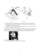
Fig.11
Fig.12-a
⚫
a, install arm I into fixed seat R with M16 screw S, washer N, M16 screw Q, and fasten as Fig.11
⚫
b, install cylinder pin , insert Pin J into the hole of I , let rod K goes into J, fasten with M18 screw H,
install washer L and screw M M10*16 as fig.11
⚫
c
,
install shovel as Fig.11, connect shovel D with E, fasten with washer F and screw M16 G, make
sure the shovel D can be swayed after installed.
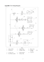
Connect air to shovel as Fig.12-a, there are three terminals A B P on the valve, Connect air with A B P on
the valve of shovel, P is air in; A is connected with connector on back cover of cylinder; B is connected
with connector on front cover of cylinder.(we also marked number 1/2/3 tell where tube should be
connected)
⚫
The other end of tube can be inserted into frame from the hole T.
Summary of Contents for CASC506
Page 14: ...13 Fig 21 Fig 22 Fig 23...
Page 25: ...24 9 Exploded drawings 9 1 Column assembly Fig 34...
Page 26: ...25 9 2 Turntable assembly Fig 35...
Page 27: ...26 9 3 Gearbox motor assembly Fig 36...
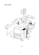
Page 28: ...27 9 4 Body assembly Fig 37...
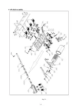
Page 29: ...28 9 5 Pedal Assembly Fig 38...
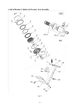
Page 30: ...29 9 6 Bead Breaker Cylinder Breaker Arm Assembly Fig 39...
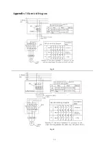
Page 31: ...30 Appendix 1 Electrical Diagram Fig 41 Fig 42...
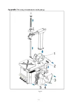
Page 33: ...32 Appendix 3 Drawing of installation for small package Fig 44...
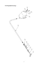
Page 38: ...37 10 8 Exploded drawings...
Page 50: ......

