14
⚫
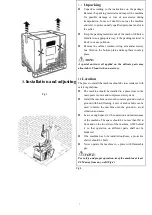
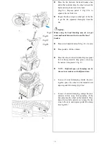
Press pedal A (Fig.18), let column back to
working position, pull back switch handle N
(Fig. 21-a), let the arm L and hex column M
move freely. Push N and press M, make
mounting head O against rim (Fig. 21-b), press
switch handle N lock arm and hex column.
Make sure mounting head keep a distance of
1~2mm from upper edge of rim and 2mm from
outer edge of rim to avoid mounting head
scratch rim.
⚫
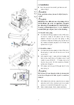
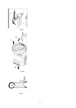
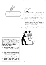
Insert lever into wheel near mounting head
(Fig. 22).
⚫
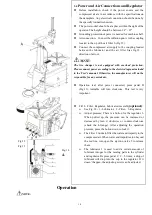
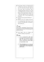
Press lever as Fig. 22-2 and press wheel as fig.
22-1, until upper edge of wheel as Fig. 23, press
lever slowly, until upper edge of wheel hang on
the mounting head.
NOTE
:
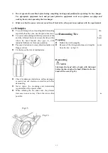
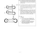
If inner tube, to avoid damage of inner tube, keep
the position of air inlet valve and mounting head
and lever as Fig. 24
.
⚫
Press pedal D (Fig. 22), turntable turn
clockwise, until edge of wheel fall off.
NOTE
:
➢
For very tough and low profile wheel,
wheel edge is easy to slip off, to avoid this,
before turn clockwise of the turntable,
may turn anti-clockwise a little to make
the turntable back 1-2mm
.
➢
If the demounting process is prevented,
stop the turntable from turning around,
lift pedal D (fig. 22), let the turntable turn
anti-clockwise.
Summary of Contents for CASC506
Page 14: ...13 Fig 21 Fig 22 Fig 23...
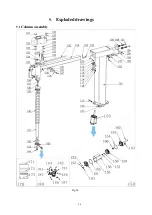
Page 25: ...24 9 Exploded drawings 9 1 Column assembly Fig 34...
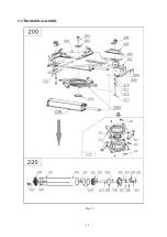
Page 26: ...25 9 2 Turntable assembly Fig 35...
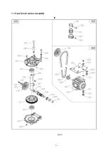
Page 27: ...26 9 3 Gearbox motor assembly Fig 36...
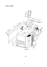
Page 28: ...27 9 4 Body assembly Fig 37...
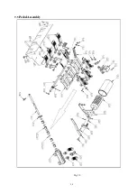
Page 29: ...28 9 5 Pedal Assembly Fig 38...
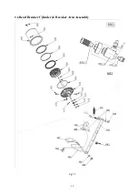
Page 30: ...29 9 6 Bead Breaker Cylinder Breaker Arm Assembly Fig 39...
Page 31: ...30 Appendix 1 Electrical Diagram Fig 41 Fig 42...
Page 33: ...32 Appendix 3 Drawing of installation for small package Fig 44...
Page 38: ...37 10 8 Exploded drawings...
Page 50: ......


