Cascadia RTOS1202709CD User Manual Download Page 13

 13

2. FRONT / REAR PANEL 
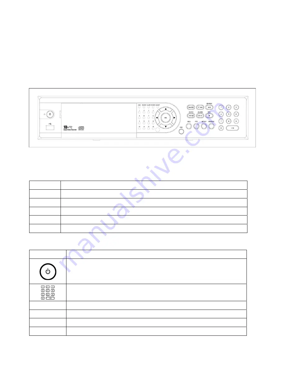
 

2-1. FRONT PANEL


Figure 2.1.1 Front panel


Table 2.1.1 LED Indication 

LED Description 

HDD 

LED light is on when the system is accessing video data. 

REC 

LED light is on when the system is recording video data. 

ALARM 

LED light is on when alarm sensors are triggered or motion is detected. 

NETWORK 

LED light is on when clients are connected to the system through the network. 

BACKUP 

LED light is on when the system save an image to a USB stick or a CD. 


Table 2.1.2 Front panel buttons 

Button Description 


Power ON/OFF button. Press to start the DVR system or to do shutdown. 

When you turn off the DVR system, it will ask for a password. The default 

password is 1111. 


Press to select a channel number or password. Press the +10 button and a 

number for selecting a channel number 10 to 16. 

SEQ 

Press to start auto sequencing of the screen in full or quad view. (Toggle) 

PTZ 

Press to control PTZ operation in live display mode. 

SETUP 

Press to launch SETUP menu. 

BACKUP 

Press to start operations involving archiving in live or playback mode. 

Summary of Contents for RTOS1202709CD

Page 1: ...This document contains preliminary information and subject to change without notice USER GUIDE RTOS1202709CD RTOS12048016CD 9 16 Channel RTOS DVR s...

Page 2: ...of used batteries according to the manufacturer s instructions This equipment and all communication wirings are intended for indoor use only To reduce the risk of fire or electric shock do not expose...

Page 3: ...reater than room ambient Therefore consideration should be given to installing the equipment in an environment compatible with the maximum ambient temperature specified by the manufacturer B Reduced A...

Page 4: ...llows Please make sure that the bellow components are included in the package If there is any missing please contact your local vendor DVR SET NETWORK CLIENT S W CD REMOTE CONTROLLER BATTERY MANUAL RU...

Page 5: ...ble Mute or Highlighted channel only LOCK Locks functions SEQ Sequence of Full or Quad view RECORD Manual recording SEARCH Search menu screen DIRECTION SELECT Direction or number 1 to 4 Enter ID DVR I...

Page 6: ...ING Video mode Video output SETTING NTSC PAL BNC VGA O X O X X O O X O X X O X O X O Do not change the setting when the power is on When the position of the switch is changed the DVR should be reboote...

Page 7: ...DD brackets to the HDD and insert rubber rings In case of installing two Hard Drives one is to be set as Master and another is as Slave Firmly insert IDE cable and power cable to the CD RW Drive and H...

Page 8: ...es of sensor to the desired sensor number You can set the type NC or NO of sensor at Setup mode ALARM OUTPUT Use this at 30V 300mA or less operating voltage and current When controlling lamp and AC op...

Page 9: ...25 3 6 SECURITY 27 3 7 NETWORK 28 3 7 1 PORT 28 3 7 2 NETWORK TYPE 29 3 7 3 DDNS 31 3 8 STORAGE 32 3 9 SAVE SETUP 32 4 LIVE SEARCH 33 4 1 Live Screen 33 4 2 SEARCH 34 4 2 1 TIME LINE Search 35 4 2 2...

Page 10: ...6 4 2 Main control panel 47 6 5 Search and Playback Viewer 48 6 5 1 Main user interface 48 6 5 2 Main control panel 49 6 5 3 Back up 50 6 6 System configuration 51 6 6 1 General 51 6 6 2 Site 52 6 6...

Page 11: ...re reliability Individual channel recording and playback with different frame rate High quality live and playback resolution Multi site management Supported by CMS application Network features remote...

Page 12: ...y password certification Video loss detection Backup Still images or AVI data into USB flash memory stick internal CD RW and Network Variety of Hard Drive Sizes up to internally 1TB 500GB HDD X 2 for...

Page 13: ...he system save an image to a USB stick or a CD Table 2 1 2 Front panel buttons Button Description Power ON OFF button Press to start the DVR system or to do shutdown When you turn off the DVR system i...

Page 14: ...in live mode It is also used as the number 1 when entering password Press to move right in the menu or to change the values in setup mode and to select camera 2 in live mode It is also used as the num...

Page 15: ...IO OUT One connector for audio output connect a headphone or a speaker RS 232 For engineering use only LAN RJ45 connector for LAN connection RS 485 422 For camera control use SENSOR IN Connector for s...

Page 16: ...recommend you protect the system by assigning a new password immediately The procedure for assigning a password is found in section 3 6 After a password has been assigned enter the password by using t...

Page 17: ...CHEDULE DEVICE ALARM OUT PTZ SPOT OUT KEY TONE REMOTE CONTROL ID SENSOR TYPE SYSTEM DVR ID DESCRIPTION LANGUAGE LOAD FACTORY DEFAULT LOAD DEFAULT DATE FORMAT SET DATE TIME SECURITY ADMIN PASSWORD USER...

Page 18: ...reen Display OSD CHANNEL Select the channel for applying the following settings by pressing the LEFT RIGHT buttons DISPLAY Enable disable display of the video channel in live display mode BRIGHTNESS C...

Page 19: ...for the specified channel Network Standard High Superior and Ultra RECORDING Assign the recording mode for each channel Continuous Motion Sensor Schedule and Disable MOTION ZONE Select Full Zone or P...

Page 20: ...ng schedule Navigate through the items to highlight using the 4 direction key buttons and set recording schedule using the SEL button Recording mode in schedule COPY FROM Select a channel number by pr...

Page 21: ...bar corresponds with one hour DAY and Cross When a particular intersection point is highlighted selected recording mode by pressing SEL button is applied to that day and the time zone C Continuous rec...

Page 22: ...t the spot type spot event time sequence sequence dwell time and channels KEY TONE Enable Disable button beep sound REMOTE CONTROLLER ID Select an ID of remote controller Please take steps as followin...

Page 23: ...he alarm time duration 1 255 seconds Figure 3 4 2 ALARM OUT setup screen 3 4 2 PTZ By selecting PTZ in the DEVICE menu users can set up the PTZ control options in the screen shown in figure 3 4 3 Set...

Page 24: ...d view for spot out display SPOT ON EVENT Enable disable the spot out display for event detection SPOT EVENT DWELL TIME Dwell time for spot out display on event 1 10seconds SEQUENCE Enable disable seq...

Page 25: ...MAC Address LANGUAGE Select a language Korean English Japanese Italian Russian Norwegian Czech Spanish Chinese Turkish French Finnish Dutch LOAD FACTORY DEFAULT Select ON and press the SEL button to l...

Page 26: ...26 Figure 3 5 2 DVR ID setup screen Figure 3 5 3 SYTEM Description screen Figure 3 5 4DATE TIME setup screen...

Page 27: ...3 and 4 or number keys The default password is 1111 Menu items in SECURITY ADMIN PASSWORD Set the password for the administrator The administrator can use all functions of system USER PASSWORD Set the...

Page 28: ...lect DDNS ON when you want to connect network with domain name instead of IP address DDNS NAME The DDNS sever name is ipdvrfree com Do not change the sever name Figure 3 7 1 Network setup screen 3 7 1...

Page 29: ...umeric character by pressing the LEFT and RIGHT buttons UP DOWN buttons are used to change character for each location LAN To use the LAN option when connecting the DVR to a network the following info...

Page 30: ...your network administrator Figure 3 7 3 Network setup screen DHCP ADSL To use the ADSL option when connecting the DVR to a network the following information is required If you do not have this inform...

Page 31: ...you want to connect network with domain name instead of IP address DDNS SERVER NAME The Default DDNS Server IP Address is ipdvrfree com Domain name is to be registered on ipdvrfree com Please refer t...

Page 32: ...D size recorded time LOAD SETUP FROM A USB Select ON and press the SEL button to load user defined values from a USB memory stick SAVE SETUP TO A USB Select ON and press the SEL button to save DVR sys...

Page 33: ...tinuous Recording Continuous recording in progress Manual Recording Manual recording in progress Sensor Alarm Sensor alarm recording in progress Motion Alarm Motion alarm recording in progress Remote...

Page 34: ...quencing Indicates that sequencing mode is enabled HDD Used 100 will be indicated once recorded data is full in HDD This is displayed only when OVERWRITE OFF mode which is set from storage setup Butto...

Page 35: ...urs time table Once you have selected the time zone press the SEL button to move to the 60 minutes time table and select ALL or each channel CH X for playing back the recorded video 3 Once you select...

Page 36: ...ve selected the date press the SEL button to move to the CHANNEL selector 3 Use the LEFT or RIGHT button to change the channel selection from ALL to any of the four available channels 4 Once you have...

Page 37: ...playback the selected video 4 2 3 GO TO SPECIFIC TIME You can search for specified data by setting the time and date in this menu Use the LEFT or RIGHT button to move from left to right in this menu...

Page 38: ...y using the LEFT or RIGHT button to navigate through the day 2 Once you have selected the date press the SEL button to produce a list of instances that fit the search criteria 3 Use the LEFT and RIGHT...

Page 39: ...egin searching by using the LEFT or RIGHT button 2 Once you have selected the date press the SEL button to move to the list of recording data 3 Use the UP or DOWN button to scroll through the onscreen...

Page 40: ...menu Press to rewind the video at 1x 2x 4x and 8x speeds Jump Step backward The playback position moves 1 minute backward Press to play or pause recorded video Jump Step forward The playback position...

Page 41: ...button The PTZ function button is found on the front panel Once you press the PTZ button the screen will appear as in figure 4 4 1 Highlight the item to select and control the cameras by using the UP...

Page 42: ...r CD RW by using UP DOWN button Press SEL button to transfer the data into the storage devices If you don t transfer the data press ESC button or select NO and press SEL button Figure 5 1 1 Archive a...

Page 43: ...back recorded video Once you press the BACKUP button the screen will be displayed as shown in Figure 5 1 3 Select VIDEO by using LEFT RIGHT button and press SEL button Then the screen will ask to bac...

Page 44: ...fer the data to the storage devices If there is no enough space in the storage device the DVR will popup the message that there is no space in the storage device User can transfer images and videos in...

Page 45: ...the Network Client Software on a Window PC you can monitor real time and recorded images via optional Ethernet network This includes the ability to monitor video playback recorded video and change op...

Page 46: ...drive of your PC 2 Run client exe to start the installation process 3 Double click Network Client icon to start the client software 6 4 Live Viewer When installation is complete double click the CLIE...

Page 47: ...r recorded videos When network is connected users can playback remote data Click this icon to connect to the DVR IP Address Enter IP Address or Domain Name of DVR Port No Enter port number of DVR Prot...

Page 48: ...he search icon on the upper left of main user interface Hard Drive Storage indicator storage indicator The alarm output indicator lights up for 5 seconds if alarm output is activated on the DVR Use th...

Page 49: ...ate in Red color Click this icon to capture a still image of recorded video Save Path User can select or make a folder that captured image is saved File Enter file name of captured image File Format S...

Page 50: ...ARK OUT icon Then color of the timeline between the beginning time and ending time will be changed into dark Green 3 Next click the backup icon and the pop up window appears as below Click to play pau...

Page 51: ...figuration of Network Client Software 6 6 1 General Once you click the setup icon this pop up window appears Select security options and set a password Then when you access any of the selected functio...

Page 52: ...unction client S W will display network status Bit rate and Frame rate z Time Format Change the way the Client software displays the time 6 6 2 Site This option shows the channel information of the DV...

Page 53: ...sk space you want to allow and the save path for the log z LOG Select to save event log into log file z ICON Select to display event on live video z EVENT LIST Select to show event on Event List windo...

Page 54: ...for Always Event or Auto recording You can also select individual channels or all channels to record When you set the recording condition to event you can set event for motion or alarm with duration...

Page 55: ...to allow the program to use for recording You can also select the option to overwrite data or stop recording when the maximum amount of disk space is full C storage will be created and the data will...

Page 56: ...as follows 1 Press the SETUP button and enter the admin password 2 Go to the SECURITY and select the ADMIN PASSWORD 3 Enter the password as 12341234 and press the SEL button 4 The engineering mode sc...

Page 57: ...on our DDNS website You do not need to register with our DDNS service if you were supplied a STATIC IP address from your ISP Please check with your ISP if you are unsure of how your IP address is conf...

Page 58: ...pha and or numerical Confirm your Password Enter your Name and E Mail address 4 The registration will be complete once you click the OK button The DDNS Service Administer will send a confirmation e ma...

Page 59: ...se a Domain name Remember the ID and password you used to register with our DDNS service is separate and not the same as your Domain name You may use alpha and numerical characters as well as hyphens...

Page 60: ...our Client S W program and click the on the connect button A DVR Server Management window will appear Enter your domain name in the IP Address field at the Server Connect window Refer to your Network...

Page 61: ...nce last update is more than 5 minutes and less then 20 minutes Elapsed time since last update is more than 20 minutes No update history Modifying or deleting your Domain name Check and click Info cha...

Page 62: ...E 200GB 7200RPM 2M E IDE 250GB 7200RPM 8M E IDE MAXTER 300GB 7200RPM 16M E IDE 80GB 7200RPM 2M E IDE SAMSUNG 160GB 7200RPM 2M E IDE 160GB 7200RPM 2M E IDE 200GB 7200RPM 8M E IDE 250GB 7200RPM 8M E IDE...

Page 63: ...288 720x240 720x288 720x480 720x576 360x240 360x288 720x240 720x288 720x480 720x576 RECORDING SPEED MAX 120fps 4CH 360x240 NTSC MAX 100fps 4CH 360x288 PAL MAX 60fps 4CH 720X240 NTSC MAX 50fps 4CH 720X...

Page 64: ...2EA Max 1000GB EIDE ATA133 2EA Max 1000GB EIDE ATA133 NETWORK Still Image Video data BACKUP USB STICK CDRW Still Image Video data ELECTRONICAL POWER INPUT 100 127V 200 240V 50 60Hz ENVIRONMENTAL Oper...

Reviews: