background image

4

FAN INSTALLATION

CEILING HARDWARE 

(not to scale)

WARNING!

Support directly to building  structure only.

WARNING!

To reduce the risk of fire, electrical shock, or
personal injury, mount to outlet box marked
“Acceptable for Ceiling Fan Support” using the
mounting hardware provided with the outlet box.

Using Existing Ceiling Fixture Outlet Box

After turning the power OFF at its source (either the circuit
breaker or fuse box), lower the old fixture and disconnect
the wiring. Check the ceiling fixture outlet box to be sure
it is marked “Approved for Ceiling Fan Mounting.” If it is
not, a new box must be installed.

GETTING STARTED

Installing a New Ceiling Fixture Outlet Box

If you do not have an existing fixture located where you
wish to place your Casablanca fan, an approved ceiling
fixture outlet box must be installed and wired.

Note: The weight of this fan is 36 pounds.

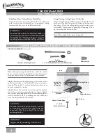
CROSSBAR MOUNTING BRACKET INSTALLATION

Note:

 After removing the old fixture, check the outlet

box to insure that it is supported by a joist or beam across
its upper surface. If not, a 2x4 stud must be installed.

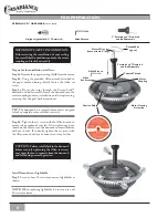
Step 1a.

 Remove the knockout plug in the center of the

outlet box or drill a 

1

/

2

-inch hole for the lag screw to pass

through. Then drill a 

1

/

4

-inch guide hole into the joist or

beam to a depth of 3 inches.

Step 1b.

Route the outlet box wires through the keyhole

slot of the crossbar mounting bracket as shown. Attach
the crossbar mounting bracket to the outlet box with the
screws provided in Pack A, making sure the outlet box
wires are not pinched by the washer.

CAUTION:

To reduce the risk of personal injury, use only
the mounting hardware provided with the
approved outlet box to install the crossbar
mounting bracket.

Crossbar Mounting Bracket

Pack A:

Lag Screw and Washer (1)

1" x 8-32 Roundhead Screws and Washers (2)

Wire Nut (4)

Joist

Ceiling-Fan-

Approved

Wiring Box

Ceiling Wiring

Crossbar Mounting

Bracket

Green Ground Wire

Ridge side down

1" x 8-32

Roundhead Screw

Washer

Summary of Contents for MIDDLEBURY

Page 1: ...on procedure MIDDLEBURY Owner s Manual READ AND SAVE THESE INSTRUCTIONS CONTENTS INTRODUCTION Before You Start 2 Safe Use 2 MOUNTING RECOMMENDATIONS General Guidelines 3 Sloped Ceiling Installations 3...

Page 2: ...the canopy hatch make sure all wires are within the canopy and that no wires are being pinched Unpacking Before assembling and installing your ceiling fan remove all parts from the shipping cartons a...

Page 3: ...f Ceiling Angle Use the tear off Ceiling Angle Template card inserted in this manual It provides you with a simple go or no go for installing your fan on a sloped ceiling When to Use Extension Poles F...

Page 4: ...R MOUNTING BRACKET INSTALLATION Note After removing the old fixture check the outlet box to insure that it is supported by a joist or beam across its upper surface If not a 2x4 stud must be installed...

Page 5: ...ket and screw into the guide hole Tighten until the outlet box is mounted firmly to the beam This box must be secured to the ceiling firmly Step 3 Attach the canopy to the crossbar mounting bracket wi...

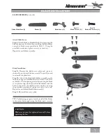
Page 6: ...Before starting the installation of your ceiling fan install the threaded downrod into the motor coupling and lock the assembly CAUTION Failure to fully lock in the downrod before securely tightening...

Page 7: ...e and screws as shown Do not discard the two screws They will be used to reinstall the plate later Step 7b Attach the blade bladeholder assembly to the motor by using two bladeholder screws from Pack...

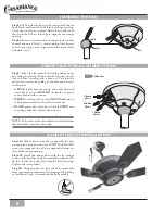
Page 8: ...er source Secure with wire nut WHITE wire from fan to white NEUTRAL wire in ceiling fixture outlet box Secure with wire nut BLACK power wire from fan to black POWER wire in ceiling outlet box Secure w...

Page 9: ...th the three screws Step 11d Securely tighten all three screws by hand only using the provided screwdriver Install Incandescent Lightbulbs Step 12 Screw in two 60 watt type A15 medium base lightbulbs...

Page 10: ...e switch Step D Insert and tighten the screws using the provided screwdriver Outer mounting holes Control Bracket Rocker Light Switch Switch Cover Plate Wall Installation Step A Locate a 2x4 wall stud...

Page 11: ...aker for at least 5 seconds Step 3 Turn the power back on at the circuit breaker and push the HIGH MED and LOW buttons in that order within 20 seconds The fan should now function properly CHANGINGTRAN...

Page 12: ...mounting plate assembly Make sure the wire nuts inside the canopy and switch housing are not touching the metal parts and that they have not fallen off the wire splices Tighten as necessary Tighten th...

Page 13: ...omplies with Part 15 of the FCC rules Operation is subject to the following two conditions 1 This device may not cause harmful interference 2 This device must accept any interference received includin...

Page 14: ...80538 FIRESIDE LIGHTING INC 970 669 3540 OWTS COLORADO SPRINGS 80903 HOME LIGHTING INC 719 471 3520 OWTS FORT COLLINS 80525 THE LIGHT CENTER 970 226 3430 OWTS LONGMONT 80501 LUMENAREA COM INC 303 485...

Page 15: ...HILLS ELECTRIC INC 402 691 4567 STATE CITY ZIP SERVICE CENTER NAME PHONE TYPE NORFOLK 68701 THE POWER STATION FROHBERG ELEC 402 371 6671 LINCOLN 68510 LINCOLN LIGHTING CTR 402 476 1297 NEVADA SPARKS 8...

Page 16: ...4704 GIDDINGS 78942 ORSAG S INC 409 542 3167 LUBBOCK 79413 ORECK VACUUMS 806 792 2821 STATE CITY ZIP SERVICE CENTER NAME PHONE TYPE ARLINGTON 76001 P M QUALITY CONT 817 478 2004 TYLER 75707 CHARLES R...

Reviews: