background image

CHAPTER-II THE CALIBRATIONS

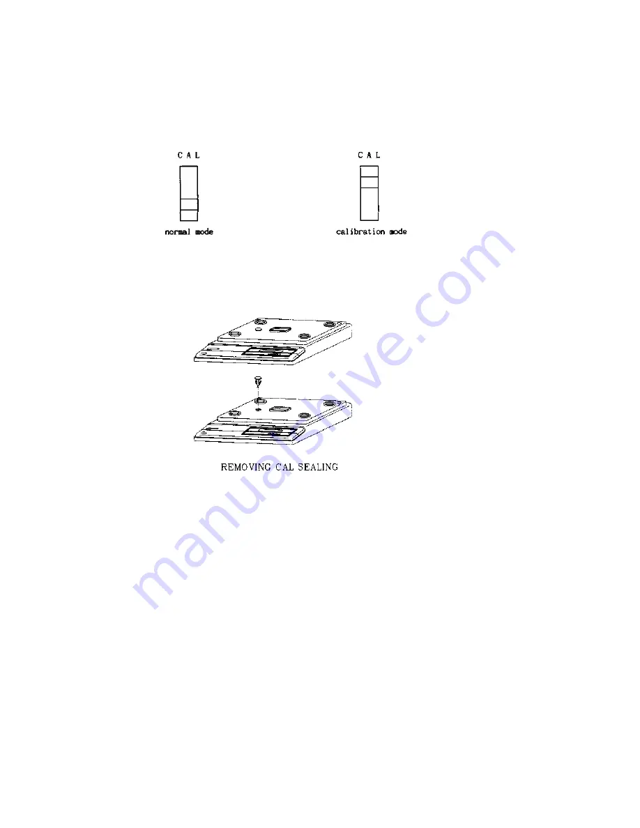
A. SET THE CALIBRATION MODE

The CAL switch is located underneath of the hole left of the upper case.

1.

Remove a seal cover.

2.

Slide CAL switch to the CAL position.

3. Plug into the AC outlet.

-> The display shows 

"CAL" 

three times.

Summary of Contents for AD series

Page 1: ...AD series SERVICE MANUAL CAS ...

Page 2: ... 3 THESPAN CALIBRATION 11 D 4 CONFIRMATIONOFTHESPAN 12 E THESPANCALIBRATIONWITHAPARTIALLOAD 13 E 1 SETTHECALIBRATIONMODE 13 E 2 ENTRYOFA PARTIAL CALIBRATION 13 E 3 INPUTOFAPARTIALLOADBYPERCENTAGE 13 E 4 THESPAN CALIBRATION 14 E 5 CONFIRMATIONOFTHESPAN 14 CHAPTER III THE PART REPLACEMENTS A REPLACEMENTOFTHELOADCELL 15 A 1 REPLACEMENTOFTHELOADCELL 15 A 2 CORRECTIONOFTHE ECCENTRICITY 15 A 3 THESPAN C...

Page 3: ...2 ERR2 23 A 3 ERR10 23 A 4 ERR11 23 A 5 ERR12 23 A 6 ERR13 23 CHAPTER VII THE OTHERS A FORTHESERIALINTERFACE 24 A 1 THECOMMUNICATION AGREEMENTS 24 A 2 THEWIRE CONNECTIONS 24 A 3 THEPROTOCOL 25 A 4 THEDATATRAINS 25 B EXPLODED VIEW 27 C FULLPARTSLIST 28 CHAPTER VIII APPENDIX I A INPUTCODESFORTHEDIGITALMODULE 32 A 1THEALTERNATIVEKEYFUNCTIONS 32 A 2INPUTS FORWEIGH CONDITION CODES 32 A 3THESPANCALIBRAT...

Page 4: ...oper operations and care of the AD series Please keepit handy for the future references B THE PRECAUTIONS 1 Check the power voltage 2 Place the scale on a flat and stable surface 3 Level the scale withfour adjusters Bubble ofthelevelshouldbecentered 4 Plug into AC outlet 10 minutes before operations 5 Keep the scale away from strong E M I noises 6 Thisscale must be installed ina dryand liquidfree ...

Page 5: ...D SEALING METHOD ...

Page 6: ...THE CALIBRATIONS A SET THE CALIBRATION MODE TheCALswitchislocatedunderneathofthehole leftof theupper case 1 Removeasealcover 2 Slide CAL switchtotheCALposition 3 PlugintotheACoutlet Thedisplayshows CAL threetimes ...

Page 7: ...B THEMODES This scale has 5 modes for set of weighing condition and for set of the spancalibration These5modes aredescribedasbelow ...

Page 8: ...r a load cell was replaced or an analog module wasreplaced Unless above both replacement skip to this mode 2 by pressing the ON OFF key B 3THEMODE3 Inthismode 3 a calibratedA D readingisshownonthe display This mode helps to do a fine span trimming without span calibration MODE 4 B 4THEMODE4 In this mode 4 anactual spanof the scale iscalculated by digital calibrationmethod The sign ULOAd means empt...

Page 9: ...ALIBRATIONMODE The CALswitchislocatedunderneath ofaholeleftoftheuppercase 1 Removeasealplate 2 SlideCALswitchtotheCALposition 3 PlugintotheACoutlet Thedisplay shows CAL threetimes C 2ENTRYOFTHEMODE4 Enter to span calibration mode as below ...

Page 10: ...al mode C 4 CONFIRMATION OF THE SPAN MODE 5 Thismode 5 is onlyavailable after performance of a previousspancalibrationfmode 4 1 Pressthe TARE key Thedisplay showsthe initialzeropoint 2 Pressthe ZERO keytoreadaspan netweight Thedisplayshows 0 3 Load a full weight on the platter gently Unlessthedisplayhas30 000 1 formoreaccurateweighing performafine trimming 4 If a span isbigger than 30 000 press th...

Page 11: ...is MODE 4 the display is shown ULOAd 1 Press the ON OFF key Thedisplayshowsacountdown9to0 LOAd is shown on the display 2 Loadafullweightontheplattergently 3 Press the ON OFF key Thedisplayshows acountdownagain The displayshows End andbe blanked 4 Removea fullloadfrom the platter If you want to quit this span calibration press the ZERO key while either ULOAd or LOAd isshownonthedisplay With above o...

Page 12: ...ng perform fine trimming 4 If a span is bigger than 30 000 press the or kg lb key twice for a decreasing and less than 30 000 press the or kg lb key and touch the TARE key for an increasing Whenever you press these keys a count can be changed 5 At the end of fine trimming press the ON OFF key 6 Pressthe ZERO key to exit andgotothe normal mode Weightdisplayshows Err2 butactuallythiserrormessageisno...

Page 13: ... 1 Removea sealplate 2 Slide CAL switchto the CAL position 3 Plugintothe AC outlet The display shows CAL three times E 2ENTRYOFAPARTIALCALIBRATION Enter to partial span calibration mode as below E 3 INPUT A PARTIAL LOAD BY PERCENTAGE Inthismode below three keyshave analternative functionsrespectively Enter a desiredpartial load bypercentage using above three keys Press the ON OFF key to move to MO...

Page 14: ...CONFIRMATION OF THE SPAN MODE 5 Thismode 5 is onlyavailable after a performance of previousspancalibration mode 4 1 Pressthe TARE key Thedisplayshowsthe initialzero point 2 Pressthe ZERO keytoreadaspan netweight Thedisplayshows 0 3 Loadafull weight onthe plattergently Unlessthe displayhas30 000 1 for more accurate weighing perform fine trimming 4 If a span is bigger than 30 000 press the or kg lb ...

Page 15: ...w one A 1 6Connect aconnectorwireof the loadcell totheP C B A 1 7Place the platform onthe loadcell A 2 CORRECTION OF THE ECCENTRICITY A 2 1Set the calibration mode A 2 2SettheMODE2 CHAPTERII D 2 A 2 3 Rezero the display by pressing the ZERO key if it is needed A 2 4Put a quarter of the full weight on the platter by turnsasshown inbelow A 2 5File eachcorner which has a lessoutput thanthe others And...

Page 16: ...TION FROM REPAIR in the CHAPTER III C REPLACEMENT OF THE DIGITAL MODULE C 1 REPLACEMENTOF THEDIGITALMODULE C I IRemove the platterandthe upper case C 1 2Take a maincircuitboardout onthe body C 1 3Desolder the digitalmodule pins 48points onmainboard C 1 4Replacethedigitalmodule CDM01 byanewone C 1 5Installamainboardonthebody C 1 6Reassemble upper case andplatter C 2 THE INPUT FOR THE DIGITAL MODULE...

Page 17: ...CHAPTER IV THE TRANSFORMER A THE TRANSFORMER ...

Page 18: ...CHAPTER VI THE SCHEMATICS AND THE DIAGRAMS ...

Page 19: ...A 1 MAIN CIRCUIT DIAGRAM ...

Page 20: ......

Page 21: ...A 2 DISPLAY CIRCUIT DIAGRAM REV 00 ...

Page 22: ...B WIRING DIAGRAM REV 00 ...

Page 23: ...C PARTSLOCATION REV 00 ...

Page 24: ...isnot a real error only it promptsreturn CAL switch to the normalposition A 3 Err10 A 3 1The Err10 meansafailure oftheanalogmodule Replace the analog module by a new one For ordering call for the name CAM 01 A 4 Err11 A 4 1 The Err 11 meansa writingerror of the internal nonvolatile memory To recognize thiserror be sure tovoltages onthe circuits and doa calibration procedures Nevertheless the displ...

Page 25: ...l BAUDRATE 9 600EPS 2 DATA BIT 8 BIT 3 STOP BIT 1 BIT 4 PARITYBIT NO 5 COMMUNICATION LEVEL RS 232C LEVEL 6 DATAFORMAT ASCII 7 THECOMMANDDEFINITIONS 7 1 ENQ 05H 7 7 EOT 04H 7 2 ACK 06H 7 8 DC1 1IH 7 3 NAK 15H 7 9 DC2 12H 7 4 SOH 01H 7 10 DC3 13H 7 5 STX 02H 7 11 DC4 14H 7 6 ETX 03H A 2 THE WIRE CONNECTIONS A 2 1THE WIRECONNECTIONS OFTHE D SUB 9PIN CONNECTOROF A COMPUTER SIDE ...

Page 26: ...SOFTHESCALE SCALE ISSTABLE S NOTSTABLED U SIGN SIGNOF THEWEIGHTDATA ZERO AND POSITIVEWEIGHT NEGATIVE WEIGHT OVER LOAD F W5THROUGHWO WEIGHTDATA BUTALL F sWHENTHESCALE ISPUTONOVERLOAD UNI THROUGH UNO UNITOFWEIGHT kgORIb BCC BLOCKCHECK CHARACTER BCC IS CREATED BY EXCLUSIVE ORDERED OFA DATA BLOCK A 3THEPROTOCOL 2 THEDATA TRAINS FOR THE DC2 ...

Page 27: ...OSITIVE WEIGHT NEGATIVE WEIGHT OVERLOAD F P7THROUGHPO PRICEDATA IF THEOVERFLOWIS HAPPENINPRICE ALL F sWILL FILLTO DATA BLOCK OFTHEPRICE W5THROUGHWO WEIGHTDATA BUTALL F sWHENTHESCALEISPUTONOVERLOAD UNI THROUGH UNO UNIT OF WEIGHT kg OR Ib BCC BLOCK CHECK CHARACTER BCCIS CREATEDBY EXCLUSIVEORDERED OF EACH DATA BLOCKS ...

Page 28: ...B EXPLODEDVIEW MECHANICALPART REV 00 ...

Page 29: ......

Page 30: ......

Page 31: ...an beincreasedfrom 0 to F hexadecimal A 1 3 SHIFT Thiskeyshiftstothenext numericdigit A 1 4 ENTER Thiskeysavesthecurrentcodeorrevisedcode A 2 INPUT FOR WEIGHING CONDITION CODES A 2 1Setthescaletothecalibrationmode A 2 2 Press the ON OFF key MODE 1 The display is shown C SEt and then 1 XX A 2 3Entereachweighingconditioncode RefertoTable1through Table4 under1 3 000 ofexternalresolution THECODES FOR ...

Page 32: ...THE CODES FOR PRINTER VERSION NOTE Thisprinter interface feature isonlyavailable with CASTOPPRINTER P 202 THE CODESFOR kg lbVERSION A 3 THE SPAN CALIBRATION RefertoSPANCALIBRATIONFROMREPAIRinchapter II ...

Reviews: