CHAPTER-VIII APPENDIX-I
A. INPUT CODES FOR THE DIGITAL MODULE
A.1 THE ALTERNATIVE KEY FUNCTIONS
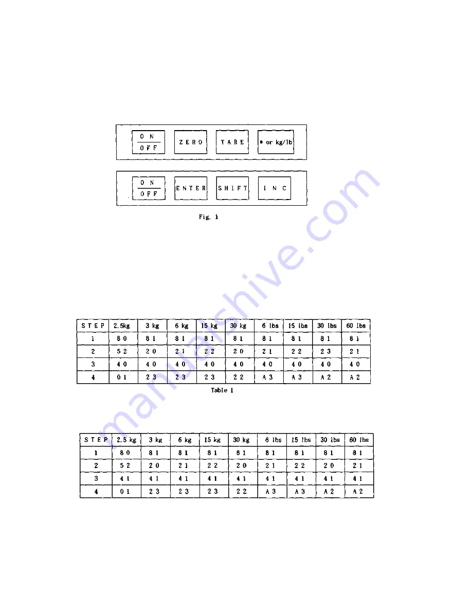
A.I.I In this mode, the functions of three key are converted as below Fig. 1.
A. 1.2 "INC" -> This key does increase the number by one at current number.
And also any numeral can be increased from "0" to "F"(hexadecimal) A. 1.3 "SHIFT" -> This key shifts to the next
numeric digit. A. 1.4 "ENTER" -> This key saves the current code or revised code.
A.2 INPUT FOR WEIGHING CONDITION CODES
A.2.1 Set the scale to the calibration mode. A.2.2 Press the " ON/OFF " key (MODE 1).
-> The display is shown " C-SEt " and then "1-XX". A.2.3 Enter each weighing condition code. Refer to Table 1 through
Table 4
under 1 / 3,000 of external resolution.
THE CODES FOR HOLD VERSION
THE CODES FOR
STANDARD
VERSION
Summary of Contents for AD series
Page 1: ...AD series SERVICE MANUAL CAS ...
Page 5: ...D SEALING METHOD ...
Page 17: ...CHAPTER IV THE TRANSFORMER A THE TRANSFORMER ...
Page 18: ...CHAPTER VI THE SCHEMATICS AND THE DIAGRAMS ...
Page 19: ...A 1 MAIN CIRCUIT DIAGRAM ...
Page 20: ......
Page 21: ...A 2 DISPLAY CIRCUIT DIAGRAM REV 00 ...
Page 22: ...B WIRING DIAGRAM REV 00 ...
Page 23: ...C PARTSLOCATION REV 00 ...
Page 28: ...B EXPLODEDVIEW MECHANICALPART REV 00 ...
Page 29: ......
Page 30: ......


