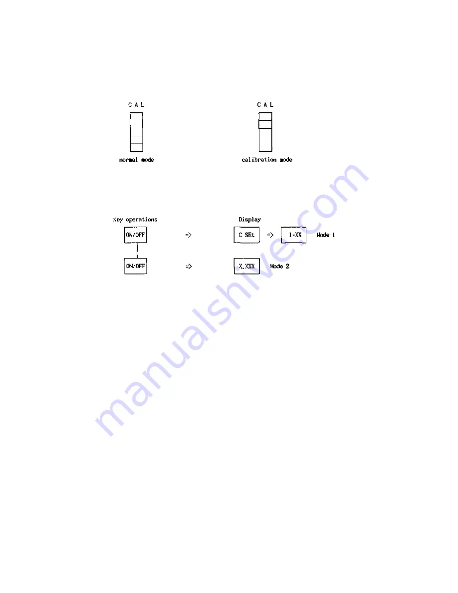
D. THE SPAN CALIBRATION FROM REPAIR D.1 SET THE
CALIBRATION MODE
The CAL switch is located underneath of a hole left of the upper case.
1.
Remove a seal plate.
2.
Slide CAL switch to the CAL position.
1. Press the "TAKE" key to check the initial zero point.
The initial zero point must be smaller than 20,000 counts.
2.
Press the "ZERO" key to check the span.
3.
Load a full weight on the platter gently.
The span must be bigger than 30,000 counts.
4.
Remove a full load from the platter.
5.
At the end of both checks, press the "ON/OFF" key three times
to go to the MODE 4.
D.3 THE SPAN CALIBRATIONMODE 4)
In this MODE 4, the display is shown "ULOAd".
1. Press the "ON/OFF" key,
-> The display shows a count down 9 to 0. -> "LOAd" is shown on the
display.
2.
Load a full weight on the platter gently.
3.
Press the "ON/OFF" key,
-> The display shows a count down again, -> The display shows "End" and be blanked.
4. Remove a full load from the platter.
*If you want to quit this span calibration, press the "ZERO" key while either "ULOAd " or "LOAd" is shown on the display.
With above operations, the span calibration is finished, and following paragraph B.4 guides to confirm the span and to do a fine
trimming for more accurate weighing.
However when fine trimming is not needed, press the "ZERO" key to skip following MODE 5 and exit to the normal mode.
3. Plug into the AC outlet.
-> The display shows "CAL" three times.
D.2 CHECK THE INITIAL ZERO AND SPAN(MODE 2)
Summary of Contents for AD series
Page 1: ...AD series SERVICE MANUAL CAS ...
Page 5: ...D SEALING METHOD ...
Page 17: ...CHAPTER IV THE TRANSFORMER A THE TRANSFORMER ...
Page 18: ...CHAPTER VI THE SCHEMATICS AND THE DIAGRAMS ...
Page 19: ...A 1 MAIN CIRCUIT DIAGRAM ...
Page 20: ......
Page 21: ...A 2 DISPLAY CIRCUIT DIAGRAM REV 00 ...
Page 22: ...B WIRING DIAGRAM REV 00 ...
Page 23: ...C PARTSLOCATION REV 00 ...
Page 28: ...B EXPLODEDVIEW MECHANICALPART REV 00 ...
Page 29: ......
Page 30: ......


