


DC E
LECTRICAL
S
YSTEM
S
ECTION
2
28
4527 5/04
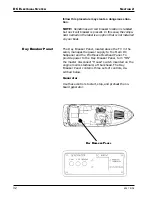
the engine room's aft bulkhead immediately aft of their
respective engine. These ON/OFF switches act as mas-
ter disconnects and must be turned to the "ON" position
before the engines can be started. Refer to the "Engine
Room Layout" portion of Section 9 for the location of
this equipment.
The voltage level within the two engine batteries is
monitored and maintained through a dedicated battery
charger. With your boat connected to a source of AC
power, this battery charger automatically maintains the
voltage levels within the two engine batteries when
their voltage drops below a predetermined level. This
battery charger is mounted on the engine room's aft,
port bulkhead just aft of the port engine. Refer to the
"Battery Chargers Engine/Gen" portion of Section 3
for more information on operating the battery charger.
Refer to the "Engine Room Layout" portion of Sec-
tion 9 for the location of this equipment.
NOTE: Each engine's alternator also maintains
the charge level within its respective battery when-
ever the engine is running.
Power to the boat's optional bow thruster is supplied
through four batteries. These four batteries are wired in
series to create a source of 24 volt power. Power from
this four 24 volt battery bank to the bow thruster con-
trols is regulated through a dedicated ON/OFF switch.
This ON/OFF switch is mounted on the engine room's
aft, port bulkhead. The ON/OFF switch acts as a master
disconnect and must be turned to the "ON" position
before the bow thruster can operate. An in-line fuse
protects the circuitry between this battery bank and the
bow thruster motor.
Voltage levels within this battery bank are regulated
though a dedicated bow thruster battery charger. This
battery charger is mounted on the engine room's aft,
port bulkhead just aft the port engine. With the Bow
Thruster Battery Charger circuit breaker on the Main
AC Subpanel "ON" and power supplied to your boat
either through shore power or the onboard generator,
the bow thruster battery charger automatically charges
the bow thruster battery bank whenever the voltage
drops below a predetermined level. Refer to the "Bow
Thruster Battery Charger" portion of Section 3 for
more information on operating the battery charger.
Battery Bank #4
Summary of Contents for 45 Voyager 2005
Page 1: ...45 Voyager Owner s Guide HIN CDR 2005 Version 1 ...
Page 2: ......
Page 4: ......
Page 8: ...PREFACE 5 01 ...
Page 32: ...22 BOATING SAFETY 4527 6 02 SECTION 1 NOTES ...
Page 33: ...23 4527 6 02 SECTION 1 BOATING SAFETY NOTES ...
Page 34: ...24 BOATING SAFETY 4527 6 02 SECTION 1 NOTES ...
Page 44: ...DC ELECTRICAL SYSTEM SECTION 2 34 4527 5 04 MAIN DC SUBPANEL ...
Page 65: ...SECTION 2 DC ELECTRICAL SYSTEM 55 4527 5 04 Revised 12 19 97 DC ELECTRICAL SYSTEM CONTINUED ...
Page 66: ...DC ELECTRICAL SYSTEM SECTION 2 56 4527 5 04 NOTES ...
Page 67: ...SECTION 2 DC ELECTRICAL SYSTEM 57 4527 5 04 NOTES ...
Page 68: ...DC ELECTRICAL SYSTEM SECTION 2 58 4527 5 04 NOTES ...
Page 80: ...AC ELECTRICAL SYSTEM SECTION 3 70 4527 5 04 AC SYSTEM MAINS PANEL ...
Page 83: ...SECTION 3 AC ELECTRICAL SYSTEM 73 4527 5 04 MAIN AC SUBPANEL ...
Page 91: ...SECTION 3 AC ELECTRICAL SYSTEM 81 4527 5 04 GFCI RECEPTACLE LOCATIONS ...
Page 95: ...SECTION 3 AC ELECTRICAL SYSTEM 85 4527 5 04 ...
Page 98: ...AC ELECTRICAL SYSTEM SECTION 3 88 4527 5 04 AC Wiring Schematic 110 Volt 60 Hz C2057D 1 ...
Page 99: ...SECTION 3 AC ELECTRICAL SYSTEM 89 4527 5 04 C2057D 2 ...
Page 100: ...AC ELECTRICAL SYSTEM SECTION 3 90 4527 5 04 AC Wiring Schematic 220 Volt 50 Hz C2058D 1 ...
Page 101: ...SECTION 3 AC ELECTRICAL SYSTEM 91 4527 5 04 C2058D 2 ...
Page 102: ...AC ELECTRICAL SYSTEM SECTION 3 92 4527 5 04 NOTES ...
Page 119: ...SECTION 4 INTERNAL SYSTEMS 109 4527 10 99 SANITATION SYSTEM C2030D B ...
Page 124: ...INTERNAL SYSTEMS SECTION 4 114 4527 10 99 GREY WATER SYSTEM ...
Page 129: ...SECTION 4 INTERNAL SYSTEMS 119 4527 10 99 NOTES ...
Page 130: ...INTERNAL SYSTEMS SECTION 4 120 4527 10 99 NOTES ...
Page 146: ...PROPULSION SECTION 5 136 4527 3 99 NOTES ...
Page 147: ...SECTION 5 PROPULSION 137 4527 3 99 NOTES ...
Page 148: ...PROPULSION SECTION 5 138 4527 3 99 NOTES ...
Page 163: ...SECTION 6 OPERATING AND MANEUVERING 153 4527 3 99 NOTES ...
Page 164: ...OPERATING AND MANEUVERING SECTION 6 154 4527 3 99 NOTES ...
Page 175: ...SECTION 7 MAINTENANCE 165 4527 8 04 ...
Page 178: ...MAINTENANCE SECTION 7 168 4527 8 04 ...
Page 185: ...SECTION 7 MAINTENANCE 175 4527 8 04 NOTES ...
Page 186: ...MAINTENANCE SECTION 7 176 4527 8 04 NOTES ...
Page 191: ...SECTION 8 WINTERIZATION AND STORAGE 181 4527 10 99 FRESH WATER SYSTEM ...
Page 196: ...WINTERIZATION AND STORAGE SECTION 8 186 4527 10 99 SANITATION SYSTEM ...
Page 205: ...SECTION 8 WINTERIZATION AND STORAGE 195 4527 10 99 IMPORTANT ANTIFREEZE BULLETIN ...
Page 206: ...WINTERIZATION AND STORAGE SECTION 8 196 4527 10 99 ...
Page 209: ...SECTION 8 WINTERIZATION AND STORAGE 199 4527 10 99 NOTES ...
Page 210: ...WINTERIZATION AND STORAGE SECTION 8 200 4527 10 99 NOTES ...
Page 216: ...WARRANTY AND PARTS SECTION 9 206 4527 5 04 Serial Number Record Sheet ...
Page 227: ...SECTION 9 WARRANTY AND PARTS 217 4527 5 04 Carver Limited Warranty ...
Page 228: ...WARRANTY AND PARTS SECTION 9 218 4527 5 04 ...
Page 231: ...INDEX 4527 3 99 Windshield washer 44 Windshield wipers 43 44 Z Zinc anodes 84 193 ...
Page 232: ...INDEX 4527 3 99 ...


