


S
ECTION
4
I
NTERNAL
S
YSTEMS
105
4527 10/99
nents. Refer to the "Bilges" portion of Section 8 for
more information on winterizing the bilges.
For safety and convenience, each bilge pump can be
operated either automatically or manually.
The bilge pumps remove almost, but not quite, all of the
water that collects within the bilges. If you want your
bilges to be completely dry, use a sponge and bucket to
remove the small amount of water that remains.
NOTE: Before operating your boat's bilge pumps, wipe
up any oil that may have accumulated in the bilge area.
Pumping oil overboard contributes to water pollution
and is in violation of the Federal Water Pollution Con-
trol Act. Violators are subject to a substantial penalty.
Automatic Operation
Each bilge pump is wired to its own circuit breaker on
the Engine Room Safety Breaker Panel and then routed
to the batteries. Incorporated into each bilge pump is a
float switch. If the pump is not already operating, the
float switch automatically turns on the appropriate
bilge pump when bilge water rises to a predetermined
level. Periodically test each switch by lifting the float,
which should turn the bilge pump on.
NOTE: The circuit breakers for the bilge pumps should
be "ON" at all times so that the pumps can operate in
automatic mode when necessary.
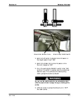
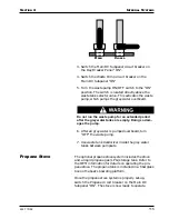
Manual Operation
The bilge pumps can also be operated manually by
using the bilge pump control switches on the Pilothouse
Overhead Panel. To manually operate the bilge pumps:
When operating a bilge pump in manual mode, you
must turn the pump "OFF" when the bilge water level
is so low that the pump can no longer drain it. Allow-
ing the pump to operate when it is not pumping water
could seriously damage the pump.
1. Switch the Auto Bilge Pump circuit breakers on the
Engine Room Safety Panel "ON".
Bilge Pump
Operation
A T
IP
F
ROM
C
ARVER
!
A certain amount of water al-
ways collects in your boat's
bilge, especially in the bilge area
where the shaft log is located.
The small amount of water that
normally accumulates is usually
not enough to activate an auto-
matic float switch.
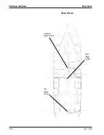
While underway and on plane,
use the helm station switches to
turn your bilge pumps on manu-
ally and let them run for 30
seconds to a minute.
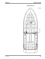
When your boat is on plane,
water in the forward and aft
bilges flows to the aft of these
bilge areas, where the bilge
pumps are located. The mid
bilge pump is near the lowest
point in the hull at rest.
Summary of Contents for 45 Voyager 2005
Page 1: ...45 Voyager Owner s Guide HIN CDR 2005 Version 1 ...
Page 2: ......
Page 4: ......
Page 8: ...PREFACE 5 01 ...
Page 32: ...22 BOATING SAFETY 4527 6 02 SECTION 1 NOTES ...
Page 33: ...23 4527 6 02 SECTION 1 BOATING SAFETY NOTES ...
Page 34: ...24 BOATING SAFETY 4527 6 02 SECTION 1 NOTES ...
Page 44: ...DC ELECTRICAL SYSTEM SECTION 2 34 4527 5 04 MAIN DC SUBPANEL ...
Page 65: ...SECTION 2 DC ELECTRICAL SYSTEM 55 4527 5 04 Revised 12 19 97 DC ELECTRICAL SYSTEM CONTINUED ...
Page 66: ...DC ELECTRICAL SYSTEM SECTION 2 56 4527 5 04 NOTES ...
Page 67: ...SECTION 2 DC ELECTRICAL SYSTEM 57 4527 5 04 NOTES ...
Page 68: ...DC ELECTRICAL SYSTEM SECTION 2 58 4527 5 04 NOTES ...
Page 80: ...AC ELECTRICAL SYSTEM SECTION 3 70 4527 5 04 AC SYSTEM MAINS PANEL ...
Page 83: ...SECTION 3 AC ELECTRICAL SYSTEM 73 4527 5 04 MAIN AC SUBPANEL ...
Page 91: ...SECTION 3 AC ELECTRICAL SYSTEM 81 4527 5 04 GFCI RECEPTACLE LOCATIONS ...
Page 95: ...SECTION 3 AC ELECTRICAL SYSTEM 85 4527 5 04 ...
Page 98: ...AC ELECTRICAL SYSTEM SECTION 3 88 4527 5 04 AC Wiring Schematic 110 Volt 60 Hz C2057D 1 ...
Page 99: ...SECTION 3 AC ELECTRICAL SYSTEM 89 4527 5 04 C2057D 2 ...
Page 100: ...AC ELECTRICAL SYSTEM SECTION 3 90 4527 5 04 AC Wiring Schematic 220 Volt 50 Hz C2058D 1 ...
Page 101: ...SECTION 3 AC ELECTRICAL SYSTEM 91 4527 5 04 C2058D 2 ...
Page 102: ...AC ELECTRICAL SYSTEM SECTION 3 92 4527 5 04 NOTES ...
Page 119: ...SECTION 4 INTERNAL SYSTEMS 109 4527 10 99 SANITATION SYSTEM C2030D B ...
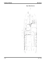
Page 124: ...INTERNAL SYSTEMS SECTION 4 114 4527 10 99 GREY WATER SYSTEM ...
Page 129: ...SECTION 4 INTERNAL SYSTEMS 119 4527 10 99 NOTES ...
Page 130: ...INTERNAL SYSTEMS SECTION 4 120 4527 10 99 NOTES ...
Page 146: ...PROPULSION SECTION 5 136 4527 3 99 NOTES ...
Page 147: ...SECTION 5 PROPULSION 137 4527 3 99 NOTES ...
Page 148: ...PROPULSION SECTION 5 138 4527 3 99 NOTES ...
Page 163: ...SECTION 6 OPERATING AND MANEUVERING 153 4527 3 99 NOTES ...
Page 164: ...OPERATING AND MANEUVERING SECTION 6 154 4527 3 99 NOTES ...
Page 175: ...SECTION 7 MAINTENANCE 165 4527 8 04 ...
Page 178: ...MAINTENANCE SECTION 7 168 4527 8 04 ...
Page 185: ...SECTION 7 MAINTENANCE 175 4527 8 04 NOTES ...
Page 186: ...MAINTENANCE SECTION 7 176 4527 8 04 NOTES ...
Page 191: ...SECTION 8 WINTERIZATION AND STORAGE 181 4527 10 99 FRESH WATER SYSTEM ...
Page 196: ...WINTERIZATION AND STORAGE SECTION 8 186 4527 10 99 SANITATION SYSTEM ...
Page 205: ...SECTION 8 WINTERIZATION AND STORAGE 195 4527 10 99 IMPORTANT ANTIFREEZE BULLETIN ...
Page 206: ...WINTERIZATION AND STORAGE SECTION 8 196 4527 10 99 ...
Page 209: ...SECTION 8 WINTERIZATION AND STORAGE 199 4527 10 99 NOTES ...
Page 210: ...WINTERIZATION AND STORAGE SECTION 8 200 4527 10 99 NOTES ...
Page 216: ...WARRANTY AND PARTS SECTION 9 206 4527 5 04 Serial Number Record Sheet ...
Page 227: ...SECTION 9 WARRANTY AND PARTS 217 4527 5 04 Carver Limited Warranty ...
Page 228: ...WARRANTY AND PARTS SECTION 9 218 4527 5 04 ...
Page 231: ...INDEX 4527 3 99 Windshield washer 44 Windshield wipers 43 44 Z Zinc anodes 84 193 ...
Page 232: ...INDEX 4527 3 99 ...


